Continuous transmission side discharging device of machine tool

A discharge device and continuous technology, applied in the direction of metal processing machinery parts, metal processing equipment, maintenance and safety accessories, etc., can solve the problems of waste of human resources, high risk factor, etc., and achieve the effect of reducing excessive manual judgment

Pending Publication Date: 2022-04-26
ANHUI BOMEI MACHINE TOOL
View PDF6 Cites 0 Cited by
  • Summary
  • Abstract
  • Description
  • Claims
  • Application Information

AI Technical Summary

Problems solved by technology

However, there are many transmission mechanisms on the assembly line, and the operator directly stands on the assembly line to operate, and the risk factor is high
In addition, many operators are standing on the same assembly line, which will undoubtedly cause waste of human resources

Method used


Image

  • Continuous transmission side discharging device of machine tool
  • Continuous transmission side discharging device of machine tool
  • Continuous transmission side discharging device of machine tool

Examples


Embodiment 1

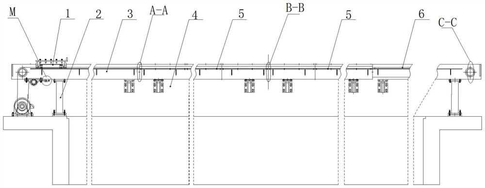
[0025] see figure 1 , the outrigger 2 is installed on the conduction plate of the side discharge device, and the underside of the outrigger 2 and the conduction plate are fixedly connected by a welding plate. When the outrigger 2 and the conduction plate are reinforced and installed, the main parts used include the inner Hexagon socket head screws, spring washers, set screws, hexagon nuts, flat washers, etc. A plurality of brackets 4 are continuously distributed on the lower side of the conduction plate. When the support 4 and the conduction plate are reinforced and installed, the main parts used include hexagon socket head cap screws, flat washers, spring washers and the like.

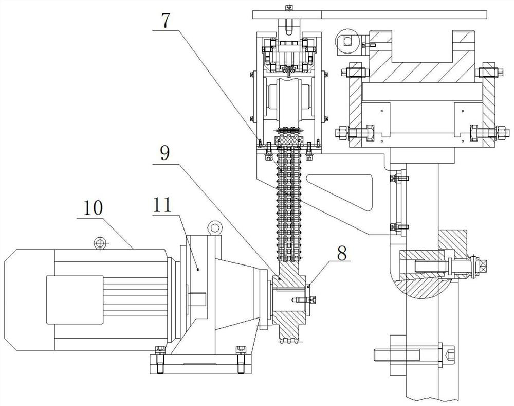
[0026] see figure 2 , the outside of the motor driving sprocket 9 is equipped with a gland 8, and the gland 8 is configured with parts such as spring washers, a plurality of hexagon socket cap screws and the like between the motor driving sprocket 9 when installing. When the cycloidal pinwheel gear...

Embodiment 2

[0033] In the present invention, the cycloidal pinwheel deceleration motor 10 drives the discharge trolley 1 to move in a directional manner. Left discharge frame 3, middle discharge frame 5, the outer position of right discharge frame 6 are all provided with discharge platform 22, when the discharge platform 22 of left discharge frame 3 positions has material [not taken off or When removing], the sensing mechanism 23 on the discharge platform 22 at the 3rd position of the left discharge frame detects that there is material on the discharge platform 22, and the discharge trolley 1 will not stay here, and the corresponding material clamping Mechanism or pushing mechanism also can not deliver the material on the discharge trolley 1 to the discharge platform 22 of left discharge rack 3 azimuths. The discharge trolley 1 will continue to move forward, looking for a subsequent discharge platform that is not occupied by materials. In this way, in the continuous discharge process, ea...


PUM


Abstract

The invention discloses a machine tool continuous transmission side discharging device, and relates to the technical field of machine tool machining. A side discharging device is sequentially provided with a left discharging frame, a middle discharging frame and a right discharging frame, and the side discharging device is provided with a discharging trolley continuously moving on a transmission path. The left discharging frame, the middle discharging frame and the right discharging frame are provided with continuously-distributed guide rail plates, a bearing chain wheel used for conveying a chain is arranged in the area of the left discharging frame, a tensioning chain wheel used for conveying the chain is arranged in the area of the middle discharging frame, and a chain base used for steering of the chain is arranged at the most downstream end of the right discharging frame. Discharging platforms are arranged on the same sides of the left discharging frame, the middle discharging frame and the right discharging frame, and sensing mechanisms are arranged on the discharging platforms. According to the invention, excessive manual judgment and control operations are reduced during discharging and transferring, so that operators do not interfere with each other on the same production line during discharging and transferring in a continuous discharging process, and an intelligent material transferring process is realized.

Description

technical field [0001] The invention relates to the technical field of machine tool processing, in particular to a machine tool continuous transmission side discharge device. Background technique [0002] The continuous production and processing of machine tools to form an assembly line operation is an important way to improve the production efficiency of machine tools. After the machine tool produces and processes materials, it outputs the materials. When passing through the assembly line, sometimes it is necessary to transfer the materials from the assembly line. Now many factories, Workshops rely on manpower to transfer materials out of the assembly line one by one. However, there are many transmission mechanisms on the assembly line, and the operator directly stands on the assembly line to operate, and the risk factor is relatively high. In addition, many operators are standing on the same assembly line, which will undoubtedly cause a waste of human resources. Therefor...

Claims


Application Information

Patent Timeline
Patent Type & Authority Applications(China)
IPC IPC(8): B23Q7/00B23Q11/00
CPCB23Q7/00B23Q11/00
Inventor 刘银秋
Owner ANHUI BOMEI MACHINE TOOL
Why Eureka
Try Eureka