Eureka AIR delivers breakthrough ideas for toughest innovation challenges, trusted by R&D personnel around the world.

Spinning machine tangential belt tensioning guide wheel and guide wheel machining method thereof

A processing method and spinning machine technology, which can be applied in spinning machines, continuous winding spinning machines, metal processing, etc., can solve the problems of large jump, unstable rotation, poor coaxiality, etc., and achieve improved strength and The effect of resilience, ensuring production demand, and improving product quality

Pending Publication Date: 2022-04-26
浙江机电职业技术学院
View PDF0 Cites 0 Cited by
  • Summary
  • Abstract
  • Description
  • Claims
  • Application Information

AI Technical Summary

Problems solved by technology

The existing tensioning guide wheel is basically injection-molded by an injection molding machine, and then processed by double-top clamping and turning on a lathe to form a product. However, due to its large structure, long length, and thin wall thickness, the spinning wheel now processed by turning The tensioning guide wheel of the yarn dragon belt has problems such as large runout, poor coaxiality, and easy deformation. The tensioning guide wheel installed on the dragon belt has problems such as superimposed jumping and unstable rotation because most of the guide wheels exist in the cooperation of the dragon belt. , reduce the transmission accuracy and service life of the dragon belt, and affect the twisting quality and molding quality of the yarn. Meet the needs of high-speed spinning machines

Method used


Image

  • Spinning machine tangential belt tensioning guide wheel and guide wheel machining method thereof
  • Spinning machine tangential belt tensioning guide wheel and guide wheel machining method thereof
  • Spinning machine tangential belt tensioning guide wheel and guide wheel machining method thereof

Examples


Embodiment Construction

[0026] The specific embodiments of the present invention are described in detail below in conjunction with the accompanying drawings.

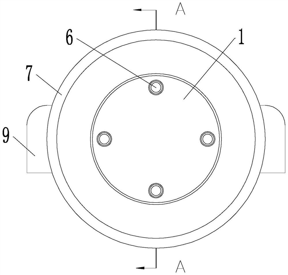
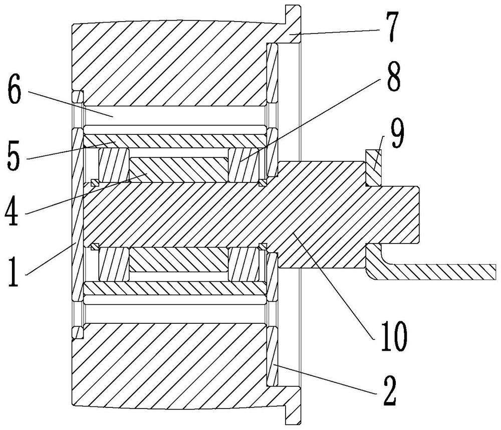
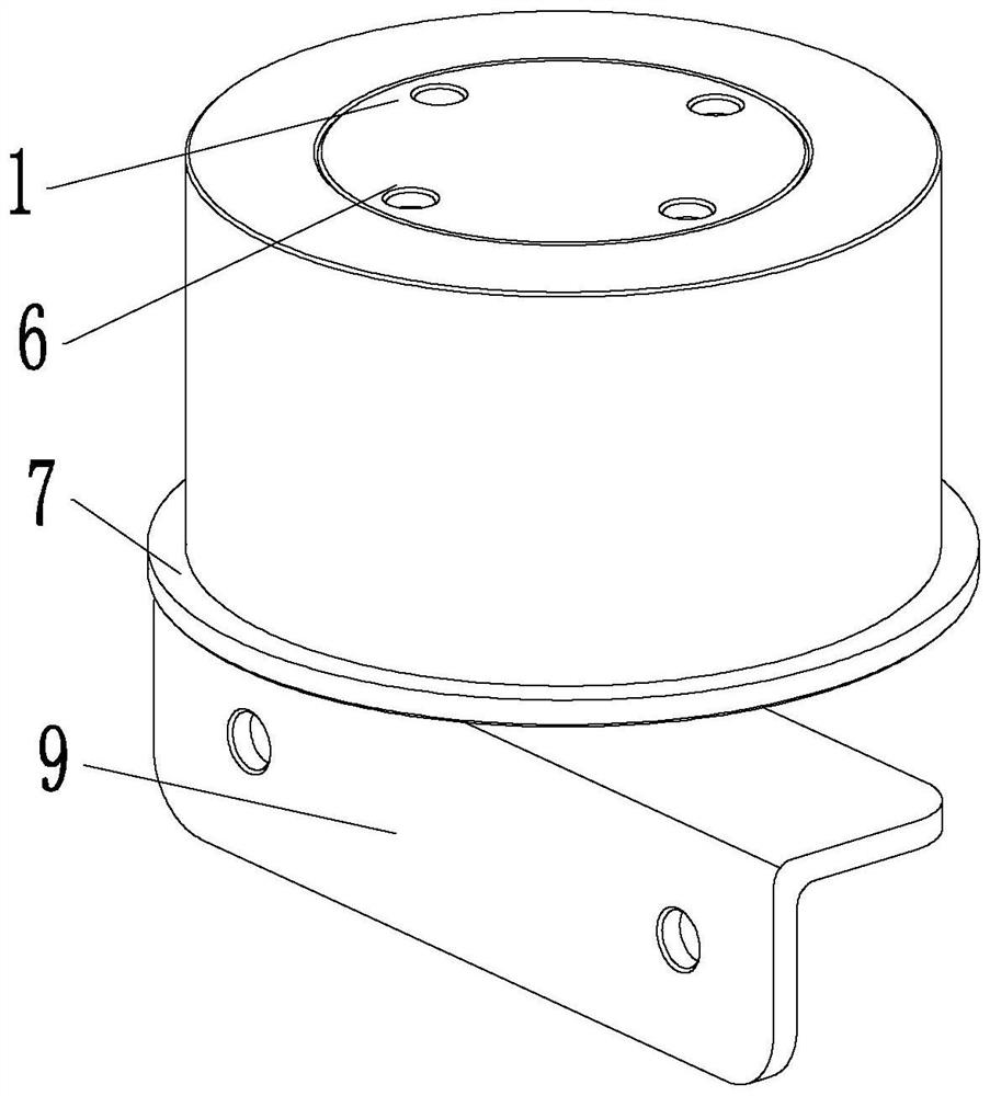
[0027] as Figures 1 to 4 As shown, the tension guide wheel of the present invention comprises a guide wheel matrix, the guide wheel base is provided in the axial direction of the transmission shaft piercing hole, the two ends of the transmission shaft piercing hole are formed separately to form the left end cover mounting counterhole and the right end cover plate mounting counterhole, the diameter of the left end cover plate mounting counterhole is less than the diameter of the right end cover plate mounting counterhole, the left end cover plate 1 and the right end cover plate 2 are fixed and installed in the left end cover mounting counterhole and the right end cover plate mounting counterhole, the transmission shaft mounting hole is set in the inner ring support sleeve 3, the inner ring support sleeve 3 is located between the left cover plate 1 ...


PUM


Abstract

The invention discloses a spinning machine tangential belt tensioning guide wheel and a guide wheel machining method thereof, and belongs to the technical field of spinning equipment parts. According to the machining method of the tensioning guide wheel, multiple times of aging treatment is conducted on the spinning tangential belt tensioning guide wheel, and the machining method of tool and tool parameter design is adopted, so that the toughness of the tensioning guide wheel can be improved in the failure treatment process, and the problems that the spinning tangential belt tensioning guide wheel is large in jumping, poor in coaxiality, prone to deformation and the like in the production process are solved; the product quality of the spinning tangential belt tensioning guide wheel is improved, and the production requirement of high-quality yarn is met. According to the tensioning guide wheel, the inner ring sleeve is arranged on the base body of the tensioning guide wheel, and the whole frame body of the tensioning guide wheel is formed between the inner ring sleeve and the base body of the tensioning guide wheel through integral injection molding of the reinforcing ribs, so that the strength and toughness of the tensioning guide wheel are greatly improved, jumping of the tensioning guide wheel can be reduced during conveying of a tangential belt, and the service life of the tensioning guide wheel is prolonged. And the transmission stability of the tensioning belt wheel is improved.

Description

Technical field [0001] The present invention belongs to the technical field of textile equipment components, in particular with a spinning machine dragon belt tension guide wheel and its guide wheel processing method is related. Background [0002] The dragon belt is one of the important components in the spinning machine, mainly used for friction drive cross-winding cylinders that rotate in the winding frame mounted on the winding device. The existing dragon belts are rotating circuits formed by supporting multiple tightening guide wheels. The existing tightening guide wheel basically uses injection molding machine injection molding, by the lathe double top clamping turning processing to form a product, and due to its larger structural shape, longer length and thiner wall thickness and other reasons, the spinning dragon belt tightening guide wheel of the current turning processing has large jumping, poor coaxiality, easy deformation and other problems, in the tightening guide w...

Claims


Application Information

Patent Timeline
Patent Type & Authority Applications(China)
IPC IPC(8): B29D99/00B29C45/00B26F1/16D01H1/20B29K77/00
CPCB29D99/0032B29C45/0055B26F1/16D01H1/20B29C2045/0058B29K2077/00
Inventor 顾其俊
Owner 浙江机电职业技术学院
Why Eureka
Eureka Blog
Learn More