Motion diversion empennage assembly and vehicle

A tail and movement technology, applied to vehicle parts, streamlined body, body, etc., can solve the problems of inability to realize the spoiler function, affect the overall flow field of the vehicle, increase the weight of the tail assembly, etc., and achieve convenient connection and positioning, and easy assembly Fast and reduce wind resistance

Active Publication Date: 2022-04-26
CHONGQING CHANGAN AUTOMOBILE CO LTD
View PDF15 Cites 0 Cited by
  • Summary
  • Abstract
  • Description
  • Claims
  • Application Information

AI Technical Summary

Problems solved by technology

[0005] A kind of empennage mechanism disclosed by CN110920760A, a kind of retractable empennage for sports utility vehicle disclosed by CN112896341A, a kind of non-embedded intelligent control automatic elevating automobile empennage disclosed by CN112550491A and a kind of embedded synchronous elevating of automobile disclosed by CN209757300U Multi-attitude smart tail fins are all capable of moving. At present, most of the plates that move with the movement mechanism in the sports tail are solid single plates. When the speed and height of the vehicle require the tail to be extended, the single plate that acts as a spoiler can withstand less air pressure. Large, easy to deform after long-term use, affecting the overall flow field of the vehicle, so that the corresponding spoiler function cannot be realized
If a higher strength material is used to manufacture the panel body, the research and development cost will be increased. If the panel body strength is increased by increasing the material thickness, the weight of the empennage assembly will increase, which is not conducive to the lightweight of the vehicle body. Therefore, it is necessary to develop a A sports spoiler assembly with a well-matched kinematic mechanism and satisfactory structural strength

Method used


Image

  • Motion diversion empennage assembly and vehicle
  • Motion diversion empennage assembly and vehicle
  • Motion diversion empennage assembly and vehicle

Examples


Embodiment Construction

[0029] The present invention will be described in detail below in conjunction with the accompanying drawings.

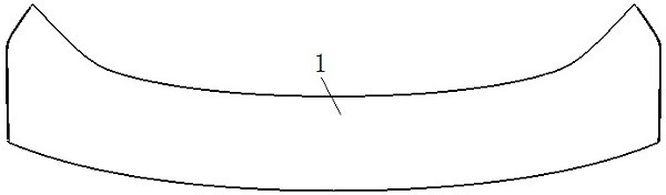
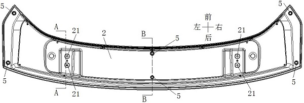
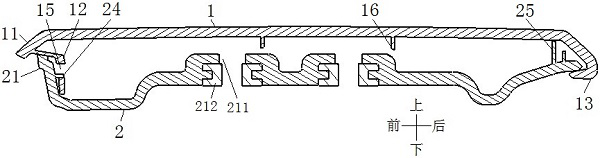
[0030] see Figure 1 to Figure 8 , the shown motion diverter empennage assembly includes an empennage body, the empennage body includes an upper plate 1 and a lower plate 2, the upper plate 1 and the lower plate 2 are buckled up and down and a strengthening chamber is formed between them, The structural strength of the empennage body itself is improved by utilizing the formed reinforcing chamber. The upper surface of the lower plate 2 is connected with a plurality of support assemblies, the support assemblies are arranged at intervals along the length direction of the empennage body, and the upper end of the support assemblies abuts against the lower surface of the upper plate 1, which further improves the structural strength of the empennage body and effectively avoids When the empennage body acts as a spoiler, it is deformed under pressure, which ensures the norma...


PUM


Abstract

The motion diversion empennage assembly comprises an empennage body, the empennage body comprises an upper plate and a lower plate, the upper plate and the lower plate are buckled up and down, a reinforcing cavity is formed between the upper plate and the lower plate, and the upper surface of the lower plate is connected with a plurality of supporting assemblies; the supporting assemblies are arranged in the length direction of the empennage body at intervals, the upper ends of the supporting assemblies abut against the lower surface of the upper plate, and a plurality of installation points connected with an empennage lifting mechanism on the back door assembly are arranged on the lower plate. The spoiler has enough structural strength, prevents the spoiler body from being pressed and deformed when playing a role in turbulent flow, and can be well matched with a movement mechanism on a back door assembly.

Description

technical field [0001] The invention relates to the technical field of vehicle empennage, in particular to a motion diversion empennage assembly and a vehicle. Background technique [0002] With the increasingly stringent emission standards, the fuel consumption of fuel vehicles has become a key problem for various car companies. Especially at high speed, due to the increase of wind resistance, the increase of rear vortex, and the increase of vehicle lift, it will lead to increased vehicle resistance, insufficient downforce at the rear of the vehicle, increased fuel consumption, and poor handling. From the perspective of aerodynamics, reducing the rear vortex, reducing the lift of the vehicle, and reducing wind resistance are the best ways to reduce fuel consumption and improve handling. [0003] Now the easiest way to reduce the vortex at the rear of the car, reduce the lift of the vehicle, and reduce the wind resistance is to add a spoiler at the rear of the car. Due to ...

Claims


Application Information

Patent Timeline
Patent Type & Authority Applications(China)
IPC IPC(8): B62D35/00
CPCB62D35/007Y02T10/82
Inventor 张永杨松松苏小平陈士昌孙晖盛俊华刘小强
Owner CHONGQING CHANGAN AUTOMOBILE CO LTD
Why Eureka
Try Eureka