Automatic case unpacking machine without damaging corrugated case
A corrugated box and unpacking machine technology, applied in packaging and other directions, can solve problems such as damage to the edges and corners of corrugated boxes, and achieve the effects of reducing friction, reducing contact area, and simple operation
- Summary
- Abstract
- Description
- Claims
- Application Information
AI Technical Summary
Problems solved by technology
Method used
Image
Examples
Embodiment 1
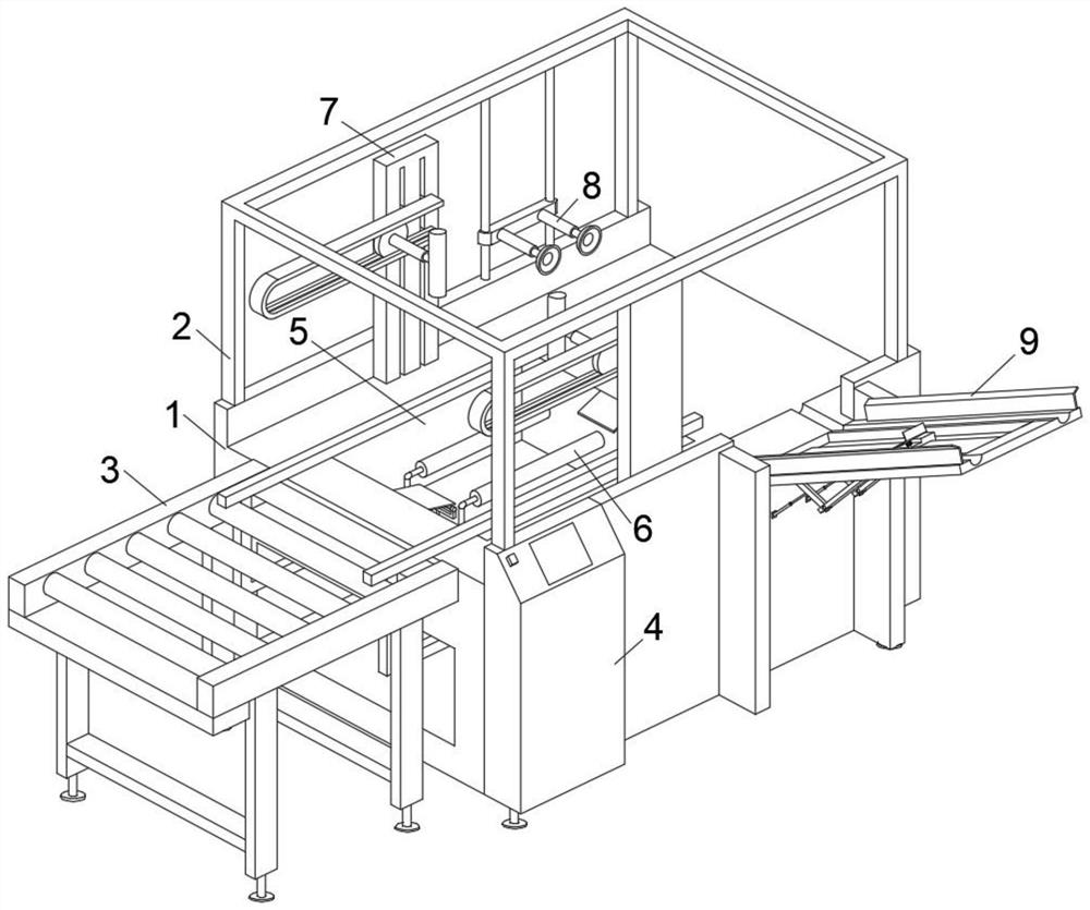
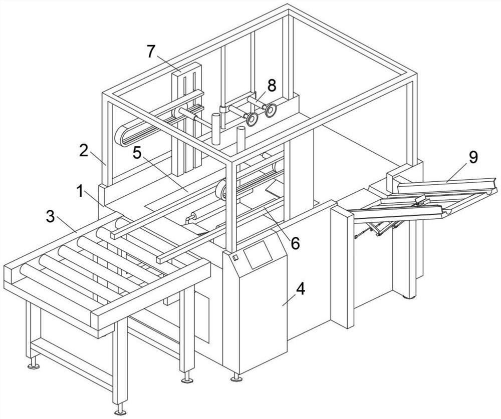
[0030] This embodiment is intended to promote solving the problem of how to ensure that the corners of corrugated boxes are not damaged when feeding, please refer to Figure 1-3 , an automatic box-opening machine that does not damage corrugated boxes, including an operating table 1 and an outer frame 2 fixedly installed on the upper end of the operating table 1, one end of the operating table 1 is provided with a detachable output belt assembly 3, the outer wall of the operating table 1 A control panel 4 is fixedly installed. The control panel 4 is used to control the entire operation of the device. A groove 5 is provided on the console 1. A folding mechanism 6 is arranged in the groove 5. The folding mechanism 6 is used to fold the bottom of the corrugated box. The folding step is carried out in the groove 5, and the side straightening roller assembly 7 and the suction cup assembly 8 are fixedly installed on the console 1, and the side straightening roller assembly 7 is locate...
Embodiment 2
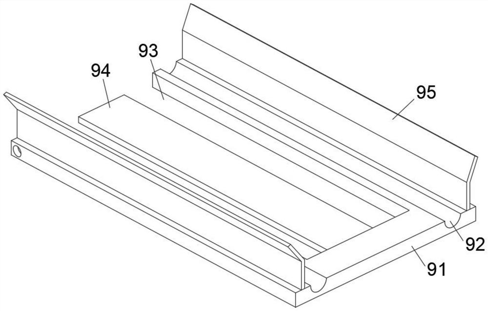
[0033] This embodiment is intended to promote the solution of how to ensure that the corrugated box remains stable during the feeding process. This embodiment is an improvement made on the basis of Embodiment 1. For details, please refer to Figure 1-4 , place plate 91 upper end both sides are fixedly installed with side baffle plate 95, offer recessed hole 93 on the place plate 91, be provided with base plate 94 in the recessed hole 93, the two ends of base plate 94 are connected with place plate 91 and console 1 respectively.
[0034] The outer wall of the operating table 1 is fixedly equipped with a movable part 96, and the movable part 96 is movably connected with a bending rocker 97, and the bending rocker 97 is movably installed with a telescopic cylinder 98, which is movably connected with the outer wall of the operating table 1. A pusher 99 is movably installed on the end of the rocking bar 97 away from the movable member 96 , and a slide groove 991 is provided on the p...
Embodiment 3
[0040] This embodiment is intended to help solve the problem of how to ensure that the carton can be transported in a straight line during the unfolding process. This embodiment is an improvement made on the basis of Embodiment 1. For details, please refer to figure 1 , figure 2 and Figure 5 , the folding mechanism 6 includes a bending connecting piece 61 located in the groove 5 and a straightening limit rod 62 fixedly installed on the bending connecting piece 61, the bending connecting piece 61 and the console 1 are close to one end of the output belt assembly 3 Interspersed connection.
[0041] There are two groups of bending connectors 61 and straightening limit rods 62, and they are arranged symmetrically with respect to the center line of the console 1. The two groups of bending connectors 61 are interspersed with threaded screw rods 63, and the screw rods 63 are externally connected. motor output.
[0042] Turn on the motor to make the screw mandrel 63 rotate clockw...
PUM
 Abstract
Description
Claims
Application Information
 - R&D
- Intellectual Property
- Life Sciences
- Materials
- Tech Scout
- Unparalleled Data Quality
- Higher Quality Content
- 60% Fewer Hallucinations
Browse by: Latest US Patents, China's latest patents, Technical Efficacy Thesaurus, Application Domain, Technology Topic, Popular Technical Reports.
© 2025 PatSnap. All rights reserved.Legal|Privacy policy|Modern Slavery Act Transparency Statement|Sitemap|About US| Contact US: help@patsnap.com


