Blast furnace uniform air supply equipment with external flow control area and method

A technology for air supply equipment and blast furnace, applied in the direction of the tuyere, can solve the problem of uneven distribution of air volume in each tuyere of the blast furnace, and achieve the effect of improving the uniformity of air volume distribution, simple structure and obvious changes.

Active Publication Date: 2022-04-26
NORTHEASTERN UNIV
View PDF9 Cites 2 Cited by
  • Summary
  • Abstract
  • Description
  • Claims
  • Application Information

AI Technical Summary

Problems solved by technology

[0004] Therefore, it is necessary to optimize a simple structure and low cost air supply equipment and method to solve the problem of uneven distribution of air volume at each tuyere of the blast furnace

Method used


Image

  • Blast furnace uniform air supply equipment with external flow control area and method
  • Blast furnace uniform air supply equipment with external flow control area and method
  • Blast furnace uniform air supply equipment with external flow control area and method

Examples


Embodiment 1

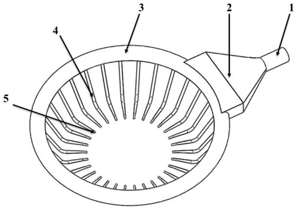
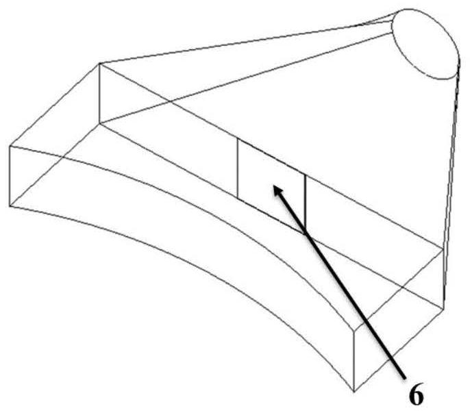
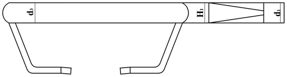
[0059] Blast furnace uniform air supply equipment with external flow control area, the structure diagram is as follows figure 1 As shown, the left view is as image 3 As shown, the left view of the hot air branch pipe and the air outlet is as follows Image 6 As shown, the structure diagram of the external flow control area of ​​the equipment is as follows figure 2 As shown, the top view of the external flow control area is as follows Figure 4 As shown, the structure of the baffle in the external flow control area Figure 5 shown. Including hot air main pipe 1, hot air surrounding pipe 3, hot air branch pipe 4, tuyere 5 and external flow control area 2. The front and rear ends of the external flow control area 2 are respectively connected with the main hot air pipe 1 and the hot air surrounding pipe 3 , and the hot air branch pipes 4 are evenly arranged along the circumference of the hot air surrounding pipe 3 , and the hot air is sent into the furnace through the tuyere...

Embodiment 2

[0081] The same as Example 1, the difference is that the expansion angle of the expansion section in the external flow control area is 80°. After the equipment runs smoothly, the standard deviation of the air volume is calculated to be 0.62. After testing, the flow velocity of the hot air after passing through the baffle is 8m / s.

Embodiment 3

[0083] Same as Example 1, the difference is that the hot air volume is increased to 4800Nm 3 / min, after the equipment runs smoothly, the standard deviation of the air volume is calculated to be 0.65. After testing, the flow rate of the hot air after passing through the baffle is 8m / s.


PUM


Abstract

The blast furnace uniform air supply equipment with the external flow control area comprises a bustle pipe, the bustle pipe is connected with a hot air main pipe through the external flow control area, a plurality of hot air branch pipes are evenly arranged in the circumferential direction of the bustle pipe, the external flow control area comprises a direct flow section and a flow expansion section, and the hot air main pipe is connected with the flow expansion section of the external flow control area. The hot air bustle pipe is connected with the external flow control area direct flow section, and a baffle is arranged between the external flow control area direct flow section and the flow expanding section. Through the specific design of the external flow control area, the kinetic energy of hot air can be weakened, so that the flow speed of the hot air entering the bustle pipe is reduced, and the air distribution uniformity of each tuyere of the blast furnace is improved.

Description

Technical field: [0001] The invention belongs to the technical field of blast furnace hot air delivery, and in particular relates to a blast furnace uniform air supply device and method with an external flow control area. Background technique: [0002] After the blast furnace hot air enters the hot blast surrounding pipe through the hot blast main pipe, it is divided into two airflows and moves along the hot blast surrounding pipe circle, and then sends the hot blast to the blast furnace through the hot blast branch pipe through the tuyeres, forming a swirl area at the front end of the tuyeres. Although the tuyeres are evenly arranged along the circumference of the furnace hearth, the wind pressure and air volume are unevenly distributed on the circumferential tuyeres, resulting in uneven size and shape of the swirl area at the front end of the tuyeres, and these inhomogeneities further affect the forward state of the blast furnace. For blast furnace smelting, the optimizati...

Claims


Application Information

Patent Timeline
Patent Type & Authority Applications(China)
IPC IPC(8): C21B7/16
CPCC21B7/163
Inventor 刘洪升史本慧罗志国邹宗树
Owner NORTHEASTERN UNIV
Why Eureka
Try Eureka