Crystal oscillator disc structure and use method thereof

A disk structure and crystal oscillator technology, which is applied in the field of OLED preparation, can solve the problems of inability to perform film forming process, time reduction, and inability to monitor speed.

Pending Publication Date: 2022-04-26
BOE TECH GRP CO LTD +1
View PDF0 Cites 0 Cited by
  • Summary
  • Abstract
  • Description
  • Claims
  • Application Information

AI Technical Summary

Problems solved by technology

Each detection probe is equipped with a crystal oscillator plate, and there are 10 crystal oscillator plates on each plate, which are distributed on the plate in a circular direction. There is only one round hole on the plate, so that a crystal oscillator is exposed, which is used as the current crystal oscillator; and the crystal oscillator is used as a consumable, and its life will gradually be exhausted with the accumulation of materials on the crystal oscillator during the process. If the detection effect drops, you need to switch to the next crystal oscillator
[0004] However, after switching to the next crystal oscillator, since the initial rate of the new crystal oscillator is 0, it will take time bef

Method used


Image

  • Crystal oscillator disc structure and use method thereof
  • Crystal oscillator disc structure and use method thereof
  • Crystal oscillator disc structure and use method thereof

Examples


Embodiment Construction

[0035] The following will clearly and completely describe the technical solutions in the embodiments of the present invention with reference to the accompanying drawings in the embodiments of the present invention. Obviously, the described embodiments are only some, not all, embodiments of the present invention. Based on the embodiments of the present invention, all other embodiments obtained by persons of ordinary skill in the art without making creative efforts belong to the protection scope of the present invention.

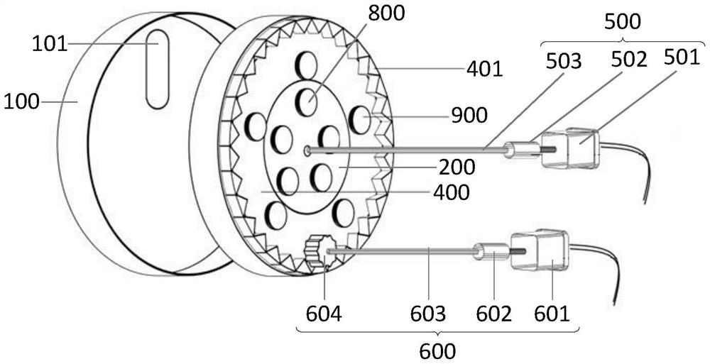
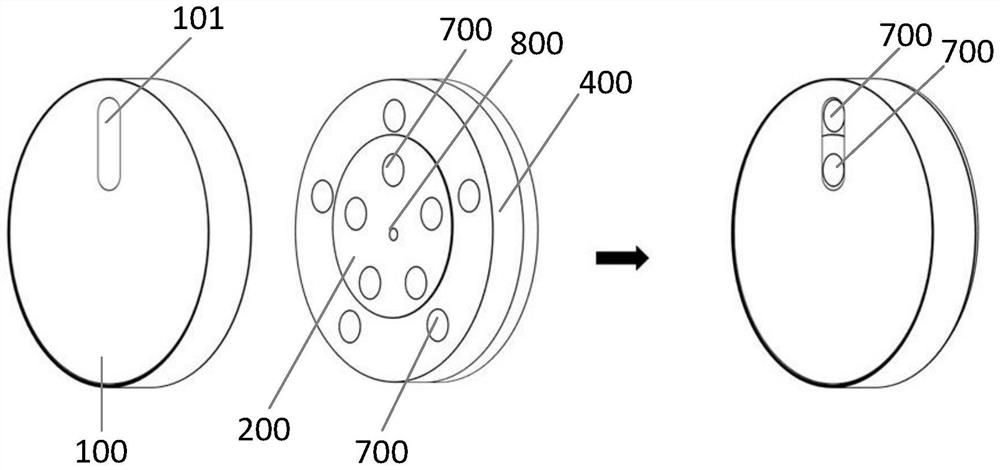
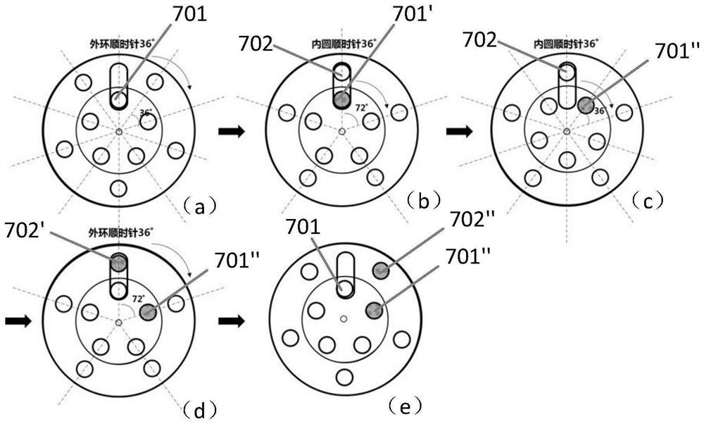
[0036] figure 1 Schematic diagram of the structure of the crystal oscillator plate structure provided by the embodiment of the present invention; figure 2 A schematic diagram of the assembly of the shell and the disc body in the crystal oscillator disc structure provided by the embodiment of the present invention; image 3 It is a schematic diagram of the steps when the crystal oscillator plate structure detects the evaporation rate provided by the embodimen...


PUM


Abstract

The invention relates to the technical field of OLED (Organic Light Emitting Diode) preparation, and discloses a crystal oscillator disc structure and a use method thereof, the structure comprises a shell, a disc body and a driving assembly; the disc body comprises an inner circle and an outer ring; the driving assembly comprises a first driving device and a second driving device, the first driving device is used for driving the inner ring to rotate, and the second driving device is used for driving the outer ring to rotate; the first surface of the inner circle is provided with a plurality of crystal oscillation sheets, the second surface of the inner circle is provided with a plurality of first electrodes, and the plurality of first electrodes and the plurality of crystal oscillation sheets arranged on the first surface of the inner circle are arranged in a one-to-one correspondence manner; the first surface of the outer ring is provided with a plurality of crystal oscillation sheets, the second surface of the outer ring is provided with a plurality of second electrodes, the plurality of second electrodes are arranged in one-to-one correspondence with the crystal oscillation sheets arranged on the first surface of the outer ring, and the first electrode and the second electrodes are used for simulating data transmission; the disc body is installed on the shell, the shell is provided with a through hole, and the through hole is used for exposing a crystal oscillator piece located on the inner circle and/or a crystal oscillator piece located on the outer ring.

Description


Claims


Application Information

Patent Timeline
Owner BOE TECH GRP CO LTD
Why Eureka
Try Eureka