
Laser power meter and method for calibrating sampling coefficient of large optical system based on laser power meter

A laser power meter and optical sampling technology, applied in the field of laser parameter detection devices, can solve problems such as inability to apply to industrial field installation and testing, inability to perform long-distance transmission, and incompetent structure, and achieve reliable and stable data transmission process and state monitoring. Smart and efficient, compact effects

Active Publication Date: 2022-04-26
XI'AN INST OF OPTICS & FINE MECHANICS - CHINESE ACAD OF SCI
View PDF4 Cites 1 Cited by
  • Summary
  • Abstract
  • Description
  • Claims
  • Application Information

AI Technical Summary

Problems solved by technology

[0007] The purpose of the present invention is to provide a laser power meter and a method for calibrating the sampling coefficient of a large optical system based on it, so as to overcome the uncompact structure existing when the existing split laser power meter is applied to the online calibration of the sampling coefficient of a large optical system in an industrial field , can not be applied to the installation and testing of industrial sites, can not be used for long-distance transmission, and the cost of calibration is high

Method used


Image

  • Laser power meter and method for calibrating sampling coefficient of large optical system based on laser power meter
  • Laser power meter and method for calibrating sampling coefficient of large optical system based on laser power meter
  • Laser power meter and method for calibrating sampling coefficient of large optical system based on laser power meter

Examples


Embodiment

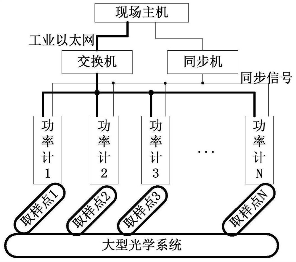
[0075] The principle block diagram of the laser power meter in this embodiment is as follows figure 1 As shown, it mainly consists of three parts: the laser optical sampling module to be tested, the photoelectric conversion analog circuit module and the digital circuit module.

[0076] The laser optical sampling module to be tested in this embodiment includes a beam pre-processing optical element, and the beam pre-processing optical element includes a reflective filter and an integrating sphere with a large attenuation ratio and high-power laser resistance. The reflective filter is installed at the light entrance of the integrating sphere. The laser to be detected is first incident on the surface of the reflective filter. The reflective filter is used as the first stage of sampling attenuation to attenuate the incident signal with a large magnification. The main reason why this embodiment chooses the reflective filter instead of the absorbing filter is that the absorbing filte...


PUM


Abstract

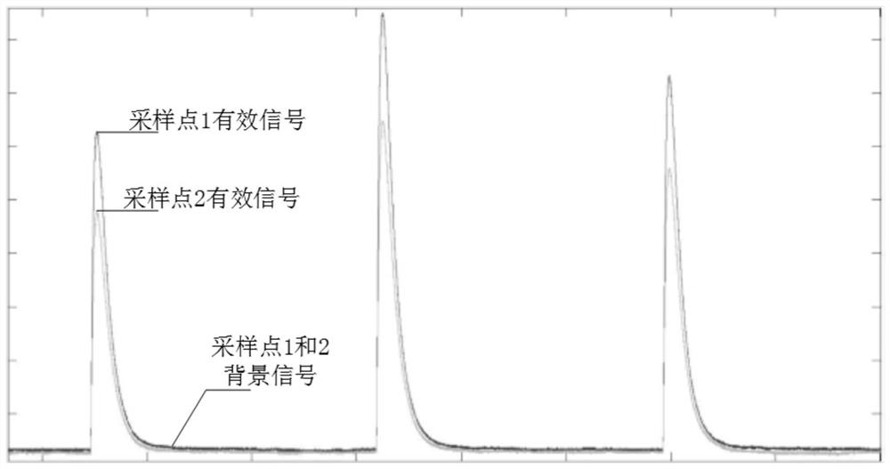
The invention relates to a laser parameter detection device, in particular to a laser power meter and a method for calibrating a sampling coefficient of a large optical system based on the laser power meter. The problems that when an existing laser power meter is applied to large optical system sampling coefficient calibration in an industrial field, the structure is not compact, installation and testing in the industrial field cannot be achieved, long-distance transmission cannot be achieved, and the calibration cost is high are solved. The laser power meter comprises a to-be-measured laser optical sampling module, a photoelectric conversion analog circuit module and a digital circuit module which are directly connected in sequence; the device is of an integrated design, is compact in structure, is easy to integrate, facilitates the installation, debugging and maintenance of an industrial field, and can be applied to the calibration of a large-scale optical system sampling coefficient. In the calibration process, the influence of background light is deducted, the interference of background stray light on sampling coefficient measurement is weakened, and the whole calculation method is simple, convenient to realize online and short in processing time. And meanwhile, due to synchronous sampling, the interference of light source fluctuation on sampling coefficient measurement can be reduced.

Description

technical field [0001] The invention relates to a laser parameter detection device, in particular to a laser power meter and a method for calibrating the sampling coefficient of a large optical system based on it. Background technique [0002] The laser power meter is an important detector for diagnosing laser parameters. At present, the laser power meter mainly adopts the split structure of "optical probe + reading meter". The optical probe and the reading meter are connected by shielded cables. The optical probe is used for The laser parameters are collected to obtain an analog signal, and the reading head is used to convert the analog signal into a digital signal, then process the digital signal to obtain the final result, and finally display the final calculation result. This structure has the following advantages: a) analog signal and digital signal are isolated, reducing circuit crosstalk noise; b) the optical probe is far away from heat sources in the electronic syste...

Claims


Application Information

Patent Timeline
Patent Type & Authority Applications(China)
IPC IPC(8): G01J1/42G01J1/04
CPCG01J1/42G01J1/0407
Inventor 余建成陈永权李刚寇经纬郑晓霞张伟刚
Owner XI'AN INST OF OPTICS & FINE MECHANICS - CHINESE ACAD OF SCI
Learn More