
Reagent analysis system for clinical laboratory of hospital and use method of reagent analysis system

An analysis system and laboratory technology, which is applied in the field of reagent analysis system for hospital laboratory to achieve the effect of increasing friction

Pending Publication Date: 2022-04-29
郝剑南
View PDF0 Cites 2 Cited by
  • Summary
  • Abstract
  • Description
  • Claims
  • Application Information

AI Technical Summary

Problems solved by technology

[0004] The purpose of the present invention is to solve the problems of manual analysis in the prior art, requiring medical staff to shake them up manually, and medical staff needing to collect and order the messy reagents, and proposes a hospital inspection system with a compact structure. Scientific reagent analysis system and using method thereof

Method used


Image

  • Reagent analysis system for clinical laboratory of hospital and use method of reagent analysis system
  • Reagent analysis system for clinical laboratory of hospital and use method of reagent analysis system
  • Reagent analysis system for clinical laboratory of hospital and use method of reagent analysis system

Examples


Embodiment 1

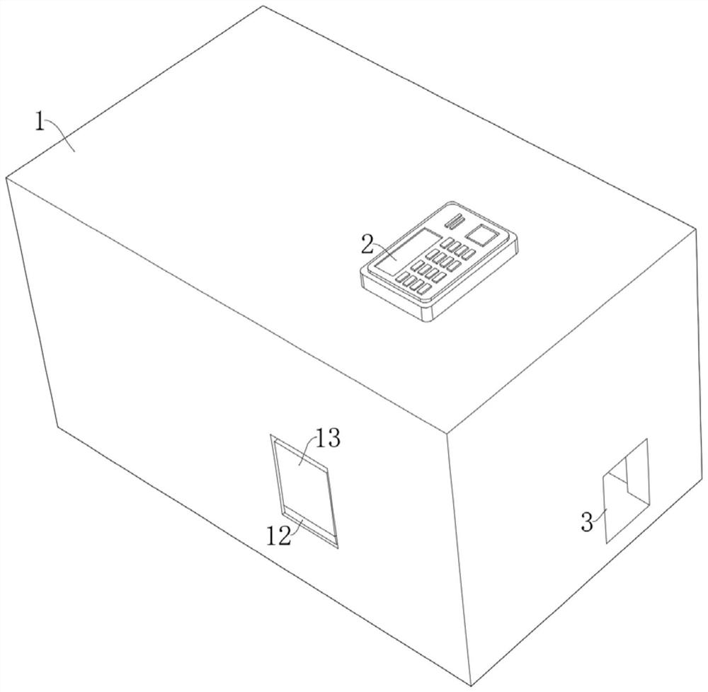
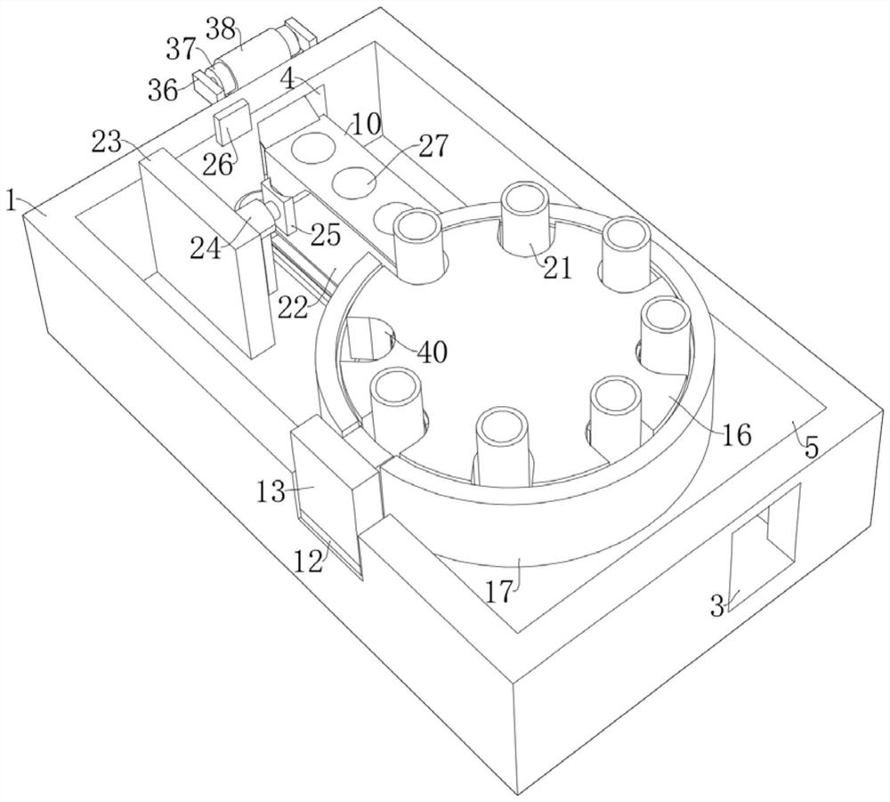
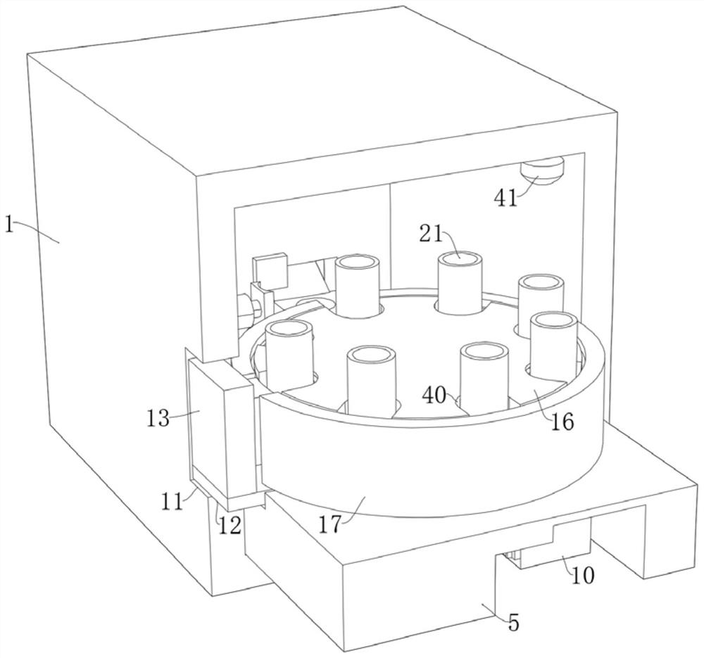
[0044] refer to Figure 1-8 , a reagent analysis system for hospital laboratories, comprising an analysis box 1 and a plurality of reagent bottles 21 located in the analysis box 1, the inner wall of the analysis box 1 is respectively provided with a first through hole 3 and a second through hole 4. The top of the analysis box 1 is fixedly connected to the control panel 2 by bolts, the bottom inner wall of the analysis box 1 is fixedly connected to the bottom plate 5 by bolts, the top of the bottom plate 5 is rotatably connected to the rotating shaft 6, and the top of the rotating shaft 6 is fixedly connected to the rotating shaft by bolts. The tray 16, the top inner wall of the analysis box 1 is fixedly connected with the analyzer 41 by bolts, the bottom inner wall of the analysis box 1 is slidably connected with the collection box 10 passing through the bottom plate 5, and the bottom plate 5 is provided with a clamping assembly for clamping the reagent bottle 21 , the top of ...

Embodiment 2

[0050] refer to Figure 1-9 , a reagent analysis system for hospital laboratories, comprising an analysis box 1 and a plurality of reagent bottles 21 located in the analysis box 1, the inner wall of the analysis box 1 is respectively provided with a first through hole 3 and a second through hole 4. The top of the analysis box 1 is fixedly connected to the control panel 2 by bolts, the bottom inner wall of the analysis box 1 is fixedly connected to the bottom plate 5 by bolts, the top of the bottom plate 5 is rotatably connected to the rotating shaft 6, and the top of the rotating shaft 6 is fixedly connected to the rotating shaft by bolts. The tray 16, the top inner wall of the analysis box 1 is fixedly connected with the analyzer 41 by bolts, the bottom inner wall of the analysis box 1 is slidably connected with the collection box 10 passing through the bottom plate 5, and the bottom plate 5 is provided with a clamping assembly for clamping the reagent bottle 21 , the top of ...


PUM


Abstract

The invention discloses a reagent analysis system for a hospital clinical laboratory and a use method of the reagent analysis system, and provides the following scheme that the reagent analysis system comprises an analysis box and a plurality of reagent bottles located in the analysis box, a first through hole and a second through hole are formed in the inner walls of the sides, away from each other, of the analysis box respectively, and a control panel is fixedly connected to the top of the analysis box; the inner wall of the bottom of the analysis box is fixedly connected with a bottom plate, the top of the bottom plate is rotatably connected with a rotating shaft, the driving motor is started to drive the first gear to rotate, the first gear can drive the rotating shaft to rotate through a gear ring, and along with rotation of the rotating shaft, the rotating disc can be driven to rotate so as to convey and analyze reagent bottles; the rotating shaft can drive the collecting box to move through cooperation of a first synchronous wheel, a second synchronous wheel, a synchronous belt and a second gear, then the reagent bottles are collected and put in order after analysis is finished, and the phenomenon that the reagent bottles are lost due to the fact that the reagent bottles are placed in a mess is avoided.

Description

technical field [0001] The invention relates to the technical field of medical devices, in particular to a reagent analysis system for a hospital laboratory and a method for using the same. Background technique [0002] Hospital laboratory departments often use reagent analysis devices to test and analyze the required reagents to determine whether they are up to standard. With continuous increase and innovation, spectrophotometers, titrators, etc. are often used in reagent analysis devices. [0003] In the prior art, when reagents are analyzed, the medical staff place the reagents in the analyzer one by one for manual analysis. Since the solution to be analyzed is often mixed unevenly, there is an error in the detection, and the medical staff needs to shake it manually , but there are many patients in the hospital, and the medical staff are lack of skills. Therefore, manual detection seriously affects the detection efficiency and increases the work intensity of the medical ...

Claims


Application Information

Patent Timeline
Patent Type & Authority Applications(China)
IPC IPC(8): B01F29/33B01F35/42
Inventor 郝剑南
Owner 郝剑南
Learn More