Self-adaptive rib plate weld joint continuous welding equipment

A self-adaptive, rib-plate technology, applied in welding equipment, auxiliary welding equipment, welding/cutting auxiliary equipment, etc., can solve the problems of manual operation, unified H-beam welding quality specifications, and low H-beam processing and production efficiency. Improve welding quality, increase the range of motion, and achieve the effect of clamping limit

Inactive Publication Date: 2022-04-29
洛阳汇成钢结构有限公司
View PDF0 Cites 0 Cited by
  • Summary
  • Abstract
  • Description
  • Claims
  • Application Information

AI Technical Summary

Problems solved by technology

[0002] With the acceleration of industrial modernization, steel structure buildings are widely used in engineering practice because of their advantages of low construction cost, energy saving and environmental protection. Therefore, H-shaped steel, which is the main support of steel structure buildings, has attracted more and more attention from the society. However, the domestic H-beam production process has not been automated and continuous. Most of the processing procedures still use manual operations, and the processing and production efficiency of H-beams is low.
[0003] In the production process of H-shaped steel, the welding process of H-shaped steel is an important step to ensure the quality of H-shaped steel. Traditionally

Method used


Image

  • Self-adaptive rib plate weld joint continuous welding equipment
  • Self-adaptive rib plate weld joint continuous welding equipment
  • Self-adaptive rib plate weld joint continuous welding equipment

Examples


Embodiment 1

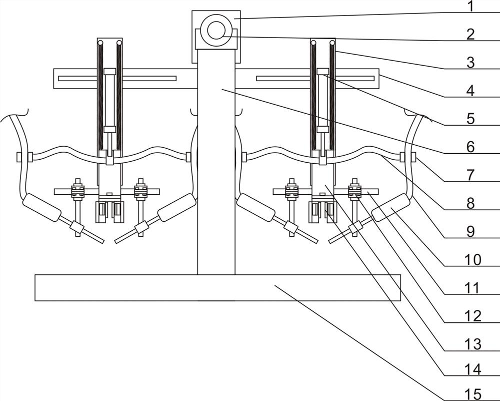
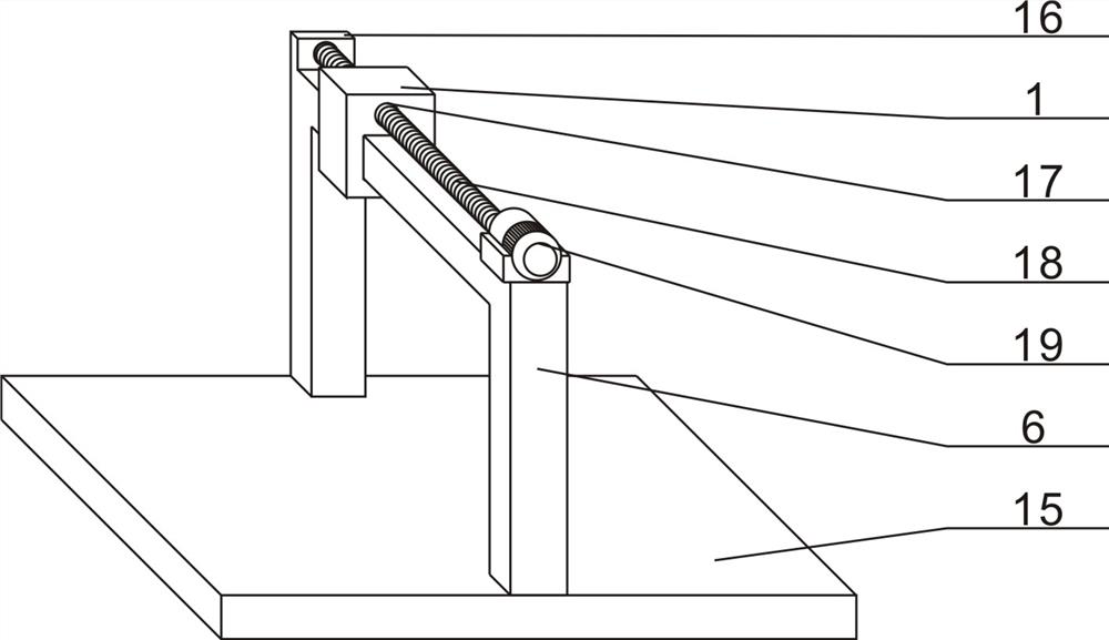
[0038] Embodiment 1, a continuous welding equipment for self-adaptive stiffened plate welds, including a bottom plate 15 and a portal frame 6. The sliding block 1 at the bottom, and the drive mechanism 2 that drives the sliding block 1 to move axially along the mandrel, specifically, the sliding block 1 is provided with a port that matches the mandrel of the portal frame 6, and the sliding block 1 passes through the The mouth sleeve is arranged on the ejector rod body, and is slidably adjusted by the driving mechanism 2. The driving mechanism 2 includes a motor 19, a baffle plate 16 and a screw rod 18. One end of the upper surface of the ejector rod body of the portal frame 6 is provided with a motor 19, and the other end is provided with a motor 19. Baffle plate 16 is arranged, and the passage upper side of sliding block 1 is provided with screw hole 17, and the output end of motor 19 is fixedly connected with the screw rod 18 that matches with screw hole 17, and the other end...

Embodiment 2

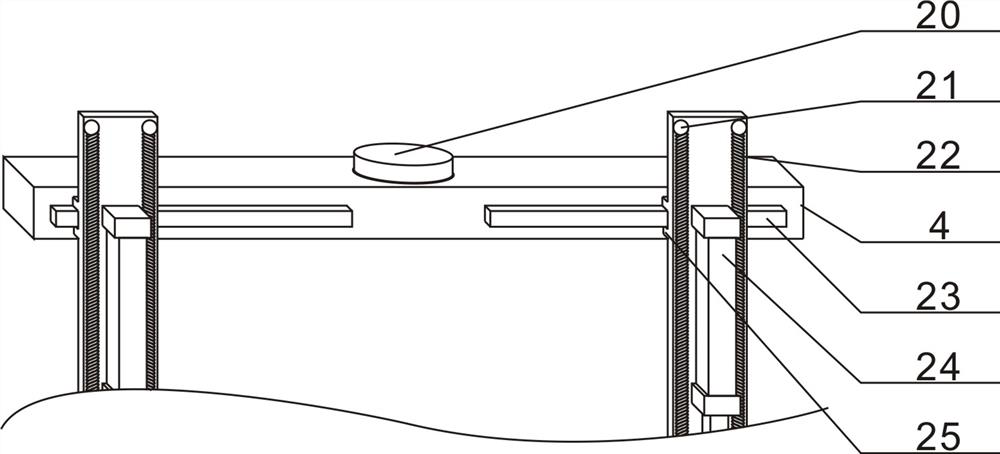
[0043] Embodiment 2, in order to reduce the moving distance of the welding frame and improve the welding quality during the continuous welding operation of the non-linear weld seam, the middle part of the upper surface of the pole 4 is provided with a rotating shaft 20, and the pole 4 is connected with the rotating shaft 20 The lower surface of the sliding block 1 is rotationally connected, and the rotational connection between the support rod and the sliding block is realized through the rotating shaft, so that the support rod can be properly rotated with the walking guidance of the guide mechanism when performing continuous welding operations on the arc-shaped ribs. Thereby ensuring the stability and high efficiency of arc continuous welding.

Embodiment 3

[0044] Embodiment 3, in the process of continuous welding operation, after the welding is completed, the guide mechanism 14 and the welding torch 10 must be de-stressed from the weld seam to realize the complete welding operation of the weld seam. However, in order to ensure the welding quality, it is often necessary to The welding seam position has been repeatedly welded, but the guiding mechanism 14 and the welding torch 10 have been separated from the welding seam position. In addition, in order to ensure the welding quality, the welding torch 10 is often on the rear side of the guiding mechanism 14. If the secondary welding operation is performed, Then it is necessary to reset the guide mechanism 14 and the welding torch 10 first, and then perform the positioning adjustment again before performing the secondary welding operation, which is very cumbersome to operate and affects the progress of the welding operation. In order to realize that the welding seam position can be re...


PUM


Abstract

A door-shaped frame is arranged on the upper portion of a bottom plate, a sliding block located on the lower portion of an ejector rod and a driving mechanism driving the sliding block to move in the axial direction of the ejector rod are arranged on an ejector rod body of the door-shaped frame, a supporting rod is arranged on the lower portion of the sliding block, and a 90-degree included angle is formed between the supporting rod and the ejector rod of the door-shaped frame. A welding frame capable of sliding in the axial direction of the supporting rod is arranged on the front face of the supporting rod, a movable plate capable of being adjusted in a lifting mode is arranged on the lower side of the front face of the welding frame, a transverse rod is arranged on the front face of the movable plate, and welding gun clamping mechanisms used for clamping welding guns and adjusting the angles of the welding guns are arranged at the two ends of a rod body of the transverse rod. The longitudinal moving supporting rod and the transverse moving welding frame are matched to form the cross-shaped running track, so that the moving range of the welding gun is greatly enlarged, and the device is suitable for continuous welding operation of straight seams and continuous welding operation of non-straight seams.

Description

technical field [0001] The invention relates to the technical field of welding equipment, in particular to a continuous welding equipment for self-adaptive stiffened plate welds. Background technique [0002] With the acceleration of industrial modernization, steel structure buildings are widely used in engineering practice because of their advantages of low construction cost, energy saving and environmental protection. Therefore, H-shaped steel, which is the main support of steel structure buildings, has attracted more and more attention from the society. However, the domestic H-beam production process has not been automated and continuous, and most of the processing procedures still use manual operations, and the processing and production efficiency of H-beam is low. [0003] In the production process of H-shaped steel, the welding process of H-shaped steel is an important step to ensure the quality of H-shaped steel. Traditionally, manual welding is used. Due to the large...

Claims


Application Information

Patent Timeline
IPC IPC(8): B23K37/02
CPCB23K37/0252
Inventor 康卫良崔峰巅杨广军
Owner 洛阳汇成钢结构有限公司
Why Eureka
Try Eureka