Thin ore body up-down medium-length hole subsequent filling mining method

A filling mining method and thin ore body technology, applied in underground mining, filling, surface mining, etc., can solve the problems of high blasting clamping, high labor intensity, low mining efficiency, etc., to reduce mining and cutting engineering, chiseling The effect of fast rock speed and high recovery efficiency

Active Publication Date: 2022-04-29
CHINA MINMETALS CHANGSHA MINING RES INST
View PDF17 Cites 0 Cited by
  • Summary
  • Abstract
  • Description
  • Claims
  • Application Information

AI Technical Summary

Problems solved by technology

[0002] When thin ore bodies are mined, the shallow hole ore retention method is generally used for mining, which has problems such as high labor intensity, low degree of mechanization, high production costs, and low mining efficiency.
In recent years, with the advancement and development of technology, for this type of ore body, it is proposed to use medium and deep holes for mining, but due to the huge limitation of equipment accuracy, YGZ90 or T150 drilling rigs are mainly used for construction, and the overall rock drilling efficiency is low. It is difficult to control the loss of dilution, and the cutting of the raised well requires manual or raised drilling rig construction, which has certain safety risks, and the amount of mining and cutting works is large, resulting in the overall recovery efficiency being inferior to the original shallow hole retention method.

Method used


Image

  • Thin ore body up-down medium-length hole subsequent filling mining method
  • Thin ore body up-down medium-length hole subsequent filling mining method
  • Thin ore body up-down medium-length hole subsequent filling mining method

Examples


Embodiment Construction

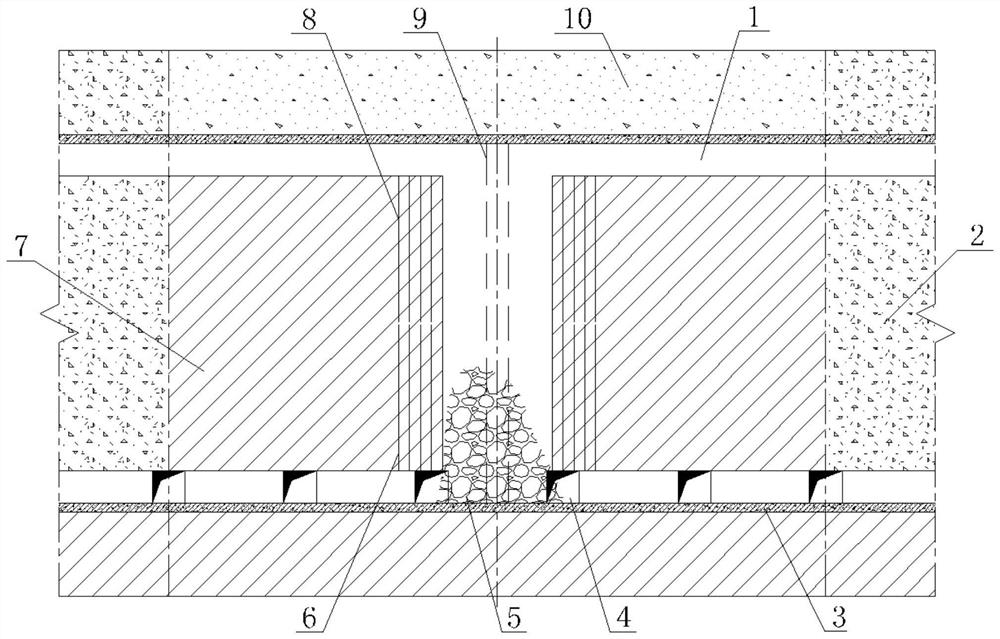
[0030] Such as figure 1 As shown, the thin ore body disclosed in this embodiment, the upper and lower middle and deep holes and subsequent filling mining method includes the following steps:

[0031] 1. Determine the structural parameters

[0032] The stope is arranged along the strike. According to the occurrence and dip angle of the ore body, determine the appropriate stope length. The width of the stope is the thickness of the ore body, and the height of the stope is the height of the middle section. The top and bottom columns are used to ensure the safe recovery of the lower middle section of the ore body.

[0033] 2. Construction mining and cutting engineering

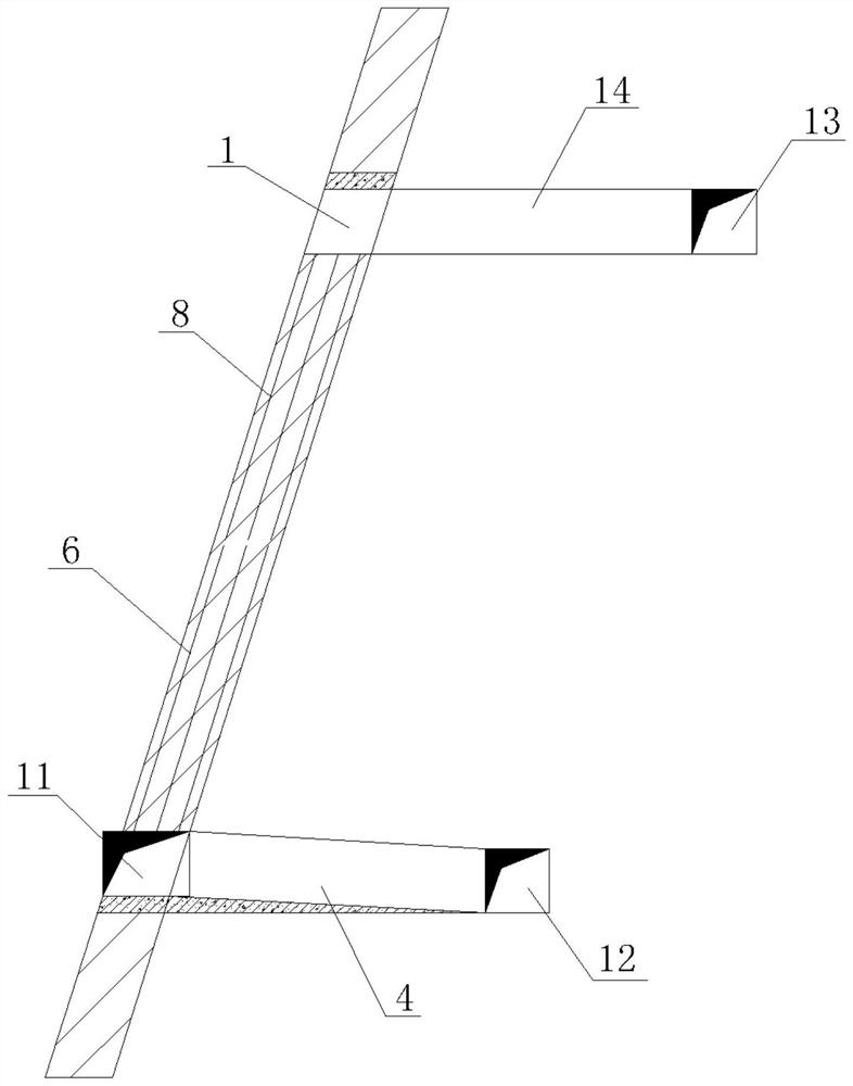
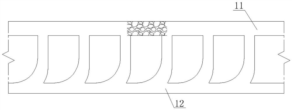
[0034] In the middle section, the roadway along the vein at the bottom will be constructed horizontally along the ore body. An artificial false bottom is constructed at the bottom of the vein lane. In the upper and middle section along the ore body, the vein roadway is constructed, and the size of the vein roa...


PUM


Abstract

The invention discloses a thin ore body up-down medium-length hole subsequent filling mining method which comprises the following steps: arranging a stope along an ore body according to the occurrence and inclination angle of the ore body without reserving top and bottom columns; stope parameters are determined; mining and cutting: horizontally constructing a bottom drift-following roadway along the ore body in the middle section, considering a bottom ore receiving roadway, a cutting roadway and a bottom rock drilling roadway along the drift-following roadway, constructing a transportation roadway outside the drift, and constructing an ore removal roadway to connect the drift-following roadway with the transportation roadway; constructing a vein-following roadway on the upper middle section along the ore body, and determining the size of the vein-following roadway according to downward rock drilling equipment and blasting parameters; the cutting courtyard is formed by two-time blasting of an upper section and a lower section; stoping is conducted, downward holes and upward holes are constructed at the same time in the upper and lower vein-following rock drilling space in a bidirectional staggered mode, all the drilled holes are parallel holes, then ore breaking is conducted in a two-time detonation mode or a sequential detonation mode, and ore drawing is conducted from an ore drawing roadway to a vein-following roadway through an outside-vein transportation roadway; and filling is conducted, all the channels are blocked, subsequent filling is conducted on the goaf, and the thin ore body can be rapidly and efficiently stoped in a low-lean-loss mode.

Description

technical field [0001] The invention belongs to the field of mine ore body mining, and in particular relates to a mining method for subsequent filling of upper, lower, middle and deep holes of a thin ore body. Background technique [0002] When thin ore bodies are mined, the shallow hole ore retention method is generally used for mining, which has problems such as high labor intensity, low degree of mechanization, high production costs, and low mining efficiency. In recent years, with the advancement and development of technology, for this type of ore body, it is proposed to use medium and deep holes for mining, but due to the huge limitation of equipment accuracy, YGZ90 or T150 drilling rigs are mainly used for construction, and the overall rock drilling efficiency is low. It is difficult to control the dilution loss, and the cutting of the raised shaft requires manual or raised drilling rig construction, which has certain safety risks. The mining and cutting work requires ...

Claims


Application Information

Patent Timeline
Patent Type & Authority Applications(China)
IPC IPC(8): E21C41/22E21F15/00E21D1/00F42D3/00F42D1/00
CPCE21C41/22E21F15/00E21D1/00F42D3/00F42D1/00
Inventor 刘东锐李向东李强朱青凌李晓辉张海云
Owner CHINA MINMETALS CHANGSHA MINING RES INST
Why Eureka
Try Eureka