Axisymmetric air inlet structure of Hall thruster
A Hall thruster and air intake structure technology, which is applied in the field of aerospace electric propulsion, can solve the problems of asymmetric discharge influence, asymmetric distribution, etc., and achieve the effect of reducing weight, releasing occupied space, and reducing axial size and length
- Summary
- Abstract
- Description
- Claims
- Application Information
AI Technical Summary
Problems solved by technology
Method used
Image

Examples
specific Embodiment approach 1
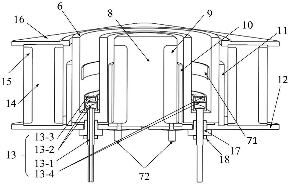
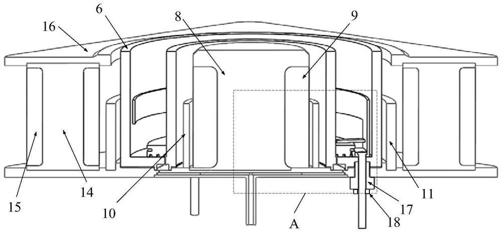
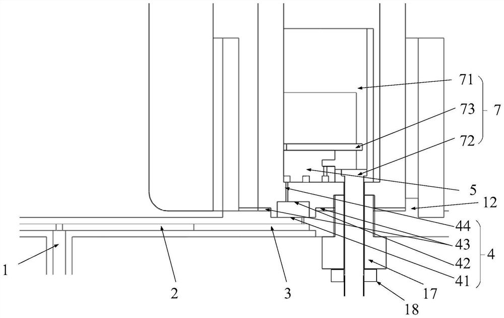
[0067] Specific implementation mode one: combine Figure 2 to Figure 4 Describe this embodiment, the axisymmetric intake structure of the Hall thruster described in this embodiment, the intake structure includes an intake pipe 1, a radial buffer chamber 3, an axial buffer chamber 4 and a gas injection structure 5 ;
[0068] The radial buffer chamber 3 includes a radial buffer chamber sink 31 , a radial buffer chamber cover plate 32 and a No. 1 air outlet 33 ;
[0069] A disk-shaped radial buffer chamber sinking groove 31 is provided at the center of the lower part of the magnetic pole bottom plate 12 of the Hall thruster, and the radial buffer chamber cover plate 32 is covered on the radial buffering gas path sinking groove 31, and the contact edge seam welding and sealing to form a complete radial buffer chamber 3, the inlet pipe 1 is vertically connected to the center of the cover plate 32 of the radial buffer chamber, and the working medium gas enters the radial buffer gas...
specific Embodiment approach 2
[0079] Embodiment 2: This embodiment further defines the axisymmetric intake structure of the Hall thruster described in Embodiment 1. In this embodiment, the axial buffer chamber 4 also includes a sealing ring 43;
[0080] Two annular grooves are provided at the bottom of the discharge channel 6, and the two annular grooves are respectively provided on both sides of the sinking groove 42 of the No. 2 axial buffer chamber. The sealing ring 43 is embedded in the two annular grooves. The sealing ring 43 is used for The junction of the second axial buffer chamber sinker 42 and the first axial buffer chamber sinker 41 is sealed.
[0081] In this embodiment, the structure also includes a mortise and tenon structure,
[0082] The No. 1 axial buffer chamber sinker 41 on the top of the magnetic pole bottom plate 12 , the No. 2 axial buffer chamber sinker 42 on the discharge channel 6 and the sealing ring 43 are connected together by a mortise and tenon structure.
specific Embodiment approach 3
[0083] Embodiment 3: This embodiment further defines the axisymmetric intake structure of the Hall thruster described in Embodiment 1. In this embodiment, the structure also includes a split air passage 2;
[0084] The split gas path 2 includes a round block, a split gas path sink 21 and a split gas path cover plate 22;
[0085] The round block is placed on the central position of the disk-shaped radial buffer chamber sinking groove 31, and a diversion air path sinking groove 21 is set in the center of the round block, and the split flow gas path sinking groove 21 communicates with the radial buffer chamber sinking groove 31;
[0086] The remaining part of the round block except for the diversion air channel sinking groove 21 is called a bump, and a gap matching the bump is provided on the radial buffer chamber cover plate 32, and a split flow is formed between every two adjacent gaps. Gas path cover plate 22;
[0087] The split air path cover plate 22 and the radial buffer c...
PUM
 Abstract
Description
Claims
Application Information
 - R&D
- Intellectual Property
- Life Sciences
- Materials
- Tech Scout
- Unparalleled Data Quality
- Higher Quality Content
- 60% Fewer Hallucinations
Browse by: Latest US Patents, China's latest patents, Technical Efficacy Thesaurus, Application Domain, Technology Topic, Popular Technical Reports.
© 2025 PatSnap. All rights reserved.Legal|Privacy policy|Modern Slavery Act Transparency Statement|Sitemap|About US| Contact US: help@patsnap.com