Magnetic field sensing device and magnetic field sensing method

A magnetic field sensing and magnetic sensor technology, applied in the field of magnetic angle sensors and sensors for measuring rotation angles, can solve the problems of reduced response bandwidth, uncertain accuracy, etc., and achieve error elimination, low delay error, and high output bandwidth Effect

Active Publication Date: 2022-04-29
SUZHOU NOVOSENSE MICROELECTRONICS
View PDF14 Cites 0 Cited by
  • Summary
  • Abstract
  • Description
  • Claims
  • Application Information

AI Technical Summary

Problems solved by technology

Generally, the sampling error for the second state output is directly proportional to the speed of the object under test, which causes uncertain accuracy problems for applications that require instantaneous angle information
[0020] In addition, if the magnetic field sensing device has a digital output, because the working mechanism of the first setting and the second setting formed by the alternate setting of the signal conditioner is used, the digital sampling output is bound to be performed alternately, so that the magnetic field sensing device The response bandwidth is bound to be reduced to 1 / 2 of the sampling bandwidth, which is an inevitable limitation for applications that require high-speed response

Method used


Image

  • Magnetic field sensing device and magnetic field sensing method
  • Magnetic field sensing device and magnetic field sensing method
  • Magnetic field sensing device and magnetic field sensing method

Examples


Embodiment 1

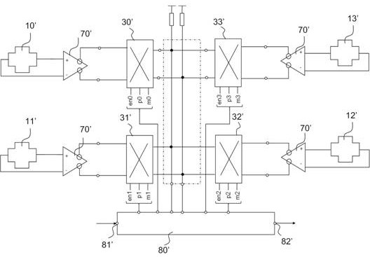
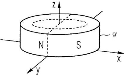
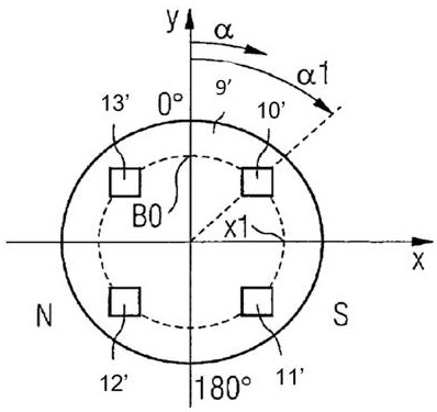
[0066] Figure 5 A schematic diagram of the circuit structure of the magnetic field sensing device of the embodiment of the invention is shown, Figure 6 Showed Figure 5 Top view structure diagram of four magnetic sensors and target magnetic field source configuration in, Figure 7 Showed Figure 5 A schematic side view of the configuration of four magnetic sensors and target magnetic field sources in.

[0067] such as Figure 5- Figure 7 As shown, the magnetic field sensing device of the embodiment of the present invention includes a first group of magnetic sensors 101 and a second group of magnetic sensors 102, at least one switching circuit 400, and an output processing circuit 600; The first group of magnetic sensors 101 and the second group of magnetic sensors 102 are located at different positions on the same plane to receive the magnetic field signals of the target magnetic field source, and each of the first group of magnetic sensors 101 and the second group of magnetic sensor...

example 1

[0076] such as Figure 11 As shown, in this embodiment, each of the magnetic sensors in the magnetic field sensing device includes two magnetic sensor units connected in parallel. For example, the first magnetic sensor unit 201 and the second magnetic sensor unit 202 are connected in parallel. The first magnetic sensor unit 201 has four electrodes, namely, electrode 301, electrode 302, electrode 303 and electrode 304. The second magnetic sensor unit 202 has four electrodes, namely, electrode 305, electrode 306, electrode 307 and electrode 308. Connecting electrode 301 and electrode 306 to form a contact 3A, connecting electrode 302 and electrode 307 to form a contact 3B, and connecting electrode 304 and electrode 305 to form a contact 3c; Connecting the electrode 303 and the electrode 308 to form a contact 3D; The contact 3A, the contact 3B, the contact 3C, and the contact 3D constitute four contacts of the magnetic sensor.

[0077] Specifically, through the switching circuit 400, ...

example 2

[0079] such as Figure 12 As shown, in this embodiment, each of the magnetic sensors in the magnetic field sensing device includes four magnetic sensor units connected in parallel. For example, the first magnetic sensor unit 201, the second magnetic sensor unit 202, the third magnetic sensor unit 203 and the fourth magnetic sensor unit 204 are connected in parallel. The first magnetic sensor unit 201 has four electrodes, namely, electrode 301, electrode 302, electrode 303 and electrode 304. The second magnetic sensor unit 202 has four electrodes, namely, electrode 305, electrode 306, electrode 307 and electrode 308. The third magnetic sensor unit 203 has four electrodes, namely, electrode 309, electrode 310, electrode 311 and electrode 312. The fourth magnetic sensor unit 204 has four electrodes, namely, electrode 313, electrode 314, electrode 315 and electrode 316. Electrode 303, electrode 306, electrode 309 and electrode 316 are connected to form a contact 3g; Electrode 301, elec...


PUM


Abstract

The invention provides a magnetic field sensing device and a magnetic field sensing method, and aims to enable each magnetic sensor in a first group of magnetic sensors and a second group of magnetic sensors to be alternately in a corresponding first working state and a second working state according to a time sequence through a switching circuit. Therefore, a signal output corresponding to the first working state and a signal output corresponding to the second working state are alternately generated, and errors caused by tiny dislocation of the radially magnetized magnetic source are eliminated. And a first differential output and a second differential output for determining angle information associated with the target magnetic field source can be obtained at the same time, so that the output processing circuit does not have a temporal difference for the formation of the final first differential output and second differential output. By adopting the technical scheme of the invention, not only is the output bandwidth higher, but also the time delay error is extremely low, and meanwhile, the characteristic of resisting external electromagnetic interference is also realized.

Description

Technical field [0001] The invention relates to the technical field of sensors for measuring rotation angles, in particular to the technical field of magnetic angle sensors. technical background [0002] Measuring the rotation angle of an object, such as the rotation axis of a gear or a mechanical device; Or measuring the position and movement information of a moving object, such as the opening and closing stroke of a valve, plays an important role in the industrial, automotive and even commercial fields. This measurement can realize the monitoring and alarm of various systems, such as idling and sliding, and various automatic action feedback control, such as action or attitude control, or the triggering of various operations. In the above application fields, magnetic sensing is often used to realize various measurements, because it has the advantages of non-contact measurement, excellent anti-vibration, anti-wear and anti-oil, and can provide sufficient accuracy and reaction spe...

Claims


Application Information

Patent Timeline
Patent Type & Authority Applications(China)
IPC IPC(8): G01B7/30G01R33/07G01R33/09
CPCG01B7/30G01R33/07G01R33/077G01R33/09
Inventor 秦文辉袁辅德
Owner SUZHOU NOVOSENSE MICROELECTRONICS
Why Eureka
Try Eureka