Image feature point calibration method and device
A technology of image feature points and calibration methods, which is applied in image analysis, image enhancement, image data processing, etc., can solve the problems of cumbersome and complex calibration equipment, and achieve high recognition efficiency, reduced computing power loss, and fast speed.
- Summary
- Abstract
- Description
- Claims
- Application Information
AI Technical Summary
Problems solved by technology
Method used
Image
Examples
Embodiment 1
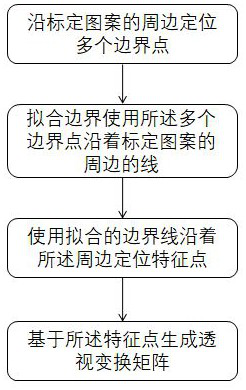
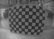
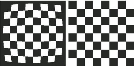
[0024] reference Figures 1 to 3, a calibration method for identifying image feature points with high efficiency, few errors and high speed, which includes capturing an image of a calibration pattern with a camera; Locate the feature points in the calibration pattern; Using feature points to locate a plurality of boundary points along the periphery of the calibration pattern; Fitting a line along the periphery of the calibration pattern using a plurality of boundary points; Use the fitted boundary line to locate feature points along the periphery; The perspective transformation matrix is generated based on the feature points, and the calibration pattern is a black-and-white square grid; The camera captures the calibration pattern by successively capturing two images for comparison. When the current two captured images are displaced, the calibration pattern is captured again. A single lens is used to continuously collect the square grid (i.e. chessboard grid) of the calibration patt...
Embodiment 2
[0034] Based on the previous embodiment, this embodiment has further improvements and differences as follows:
[0035] The camera generally includes the following program steps when shooting. The calibration method of image feature points determines the radial distortion of the camera; Determine the basic focal length of the; Determine the configuration and zoom in file; Determine the start-up delay of the system; Determine the moving speed of the camera; Determine the distribution of moving speed; Determining a zoom position curve and / or a zoom duration curve; Determine the query delay of the camera system; Or determine the minimum query interval of the camera system.
[0036] The prior art adopts the following steps to determine the radial distortion of the camera, step 1), and selects a group of feature points s recognized by the checkerboard feature point engine. Since the radial distortion away from the center of the image may be more obvious, a set of distortion feature po...
Embodiment 3
[0046] reference Figure 5 、 6 , try to calibrate the camera and the robot on the basis of embodiment 2, so as to know the relative position between the robot and the camera. This embodiment refers to the 3D robot hand eye calibration algorithm, drives the camera or calibration board to several positions through the robot, and automatically completes the calibration of the position relationship between the robot and the world coordinates and between the camera and TCP by collecting 2D photo data.
[0047] In 2D calibration, we ignore the Z value and consider everything in the 2D XY plane. The Z direction of all coordinate systems is downward (in Figure 5 、 6 In the middle, the Z direction of the bottom is upward, but the situation of the invention is different, and the bottom of the invention is downward).
[0048] The goal of 2D calibration is to obtain the 3x3 transformation matrix between systems. Each matrix has three degrees of freedom (x translation, y translation, Z rotation...
PUM
 Abstract
Description
Claims
Application Information
 - R&D
- Intellectual Property
- Life Sciences
- Materials
- Tech Scout
- Unparalleled Data Quality
- Higher Quality Content
- 60% Fewer Hallucinations
Browse by: Latest US Patents, China's latest patents, Technical Efficacy Thesaurus, Application Domain, Technology Topic, Popular Technical Reports.
© 2025 PatSnap. All rights reserved.Legal|Privacy policy|Modern Slavery Act Transparency Statement|Sitemap|About US| Contact US: help@patsnap.com


