Impact type crushing device for ore mining

A crushing device and impact-type technology, applied in earth-moving drilling, slitting machinery, vibration suppression adjustment, etc., can solve problems such as the expansion of cracked ore gaps, the need for more manpower for motor equipment, and the impact of ore mining efficiency.

Active Publication Date: 2022-05-03
武宣益德矿业有限责任公司
View PDF13 Cites 0 Cited by
  • Summary
  • Abstract
  • Description
  • Claims
  • Application Information

AI Technical Summary

Problems solved by technology

At present, when ore is mined, small-scale drill equipment is used to perform fracture mining on the mine field. Among them, the drill equipment directly contacts the surface of the mine ground, and is driven by a motor to rotate into the inside of the ore, causing the ore to be split and broken. In the process, the drill bit drills Excessive vibration will be generated when entering the mine, which requires a large amount of manpower to control the motor and the entire equipment. When the manpower is exhausted, the manpower cannot control the equipment, causing safety hazards, and when the ore is broken by this equipment, After the drill bit breaks the ore, it cannot expand the gap formed in the broken ore, so that the ore is not completely separated, which will affect the subsequent handling or crushing of the ore again. Moreover, at present, only a single drill bit is used for the cracking operation , and no other parts are used in conjunction with it, so that the drill bit will be damaged after frequent and long-term use, which affects the efficiency of ore mining, and also leads to a high frequency of maintenance or replacement of this equipment

Method used


Image

  • Impact type crushing device for ore mining
  • Impact type crushing device for ore mining
  • Impact type crushing device for ore mining

Examples


Embodiment 1

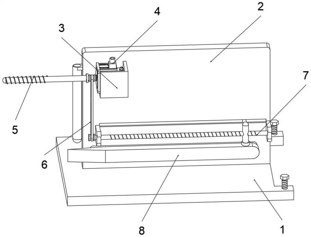
[0039] see Figure 1-Figure 4As shown, the purpose of this embodiment is to provide a crushing device for ore mining based on the impact type, at least including:

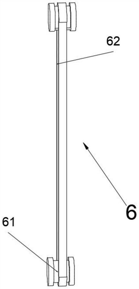
[0040] Base plate 1, fixed plate 2 is installed on the surface of base plate 1, housing 3 is installed on the surface of fixed plate 2, motor 4 is arranged inside the housing 3, one end of motor 4 is connected with rotating rod 5, one side of rotating rod 5 Protruding from the side of the bottom plate 1, the rotating rod 5 is used to break the ore;

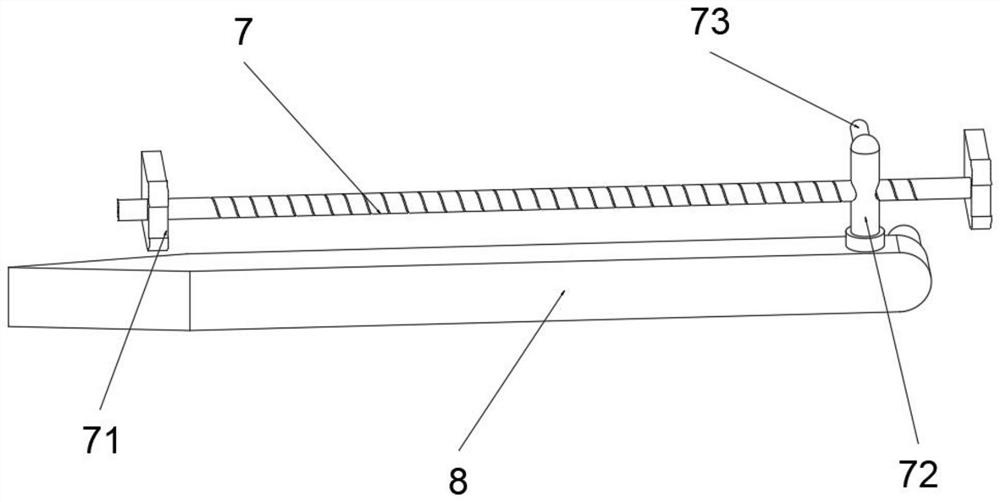
[0041] Screw mandrel 7, the end of screw mandrel 7 is provided with fixed block 71, and fixed block 71 is fixedly connected with fixed plate 2, and the surface screw thread of screw mandrel 7 is connected with screw mandrel nut 72, and screw mandrel nut 72 is provided with limiting block 73 , the limit block 73 is in contact with the fixed plate 2, the bottom of the screw nut 72 is equipped with a rupture plate 8, the rupture plate 8 and the rotating rod 5 are on the ...

Embodiment 2

[0049] Considering that the installation of the rupture plate 8 is still not up to the standard for expanding the ore gap, this embodiment makes the following improvements on the basis of embodiment 1, such as Figure 5-Figure 7 Shown:

[0050] The surface of the rupture plate 8 is oppositely provided with a concave cavity 81, and the interior of the cavity 81 is symmetrically installed with mounting blocks 82, and an inner plate 83 is hinged between the mounting blocks 82, and the inner plate 83 is used to expand the thickness of the rupture plate 8. When When the cracking plate 8 in Embodiment 1 still cannot expand the gap of ore fragmentation as far as possible during the deep process, the inner plate 83 is rotated along the hinge to make the inner plate 83 expand outward in the concave cavity 81, When the rupture plate 8 goes deep inward, when the inner plate 83 touches the gaps of the ore, the distance between the gaps will be enlarged again, so as to deepen the expansion...

Embodiment 3

[0053] Considering that the broken ore will roll onto the bottom plate 1 and affect the normal driving of the cracking plate 8, the difference between this embodiment and Embodiment 1 is that, as Figure 8-Figure 10 Shown:

[0054] The surface of the bottom plate 1 is provided with a blocking piece 9, the blocking piece 9 includes a connecting arm 91, the connecting arm 91 is in a “zigzag” shape, the surface of the fixed plate 2 is provided with a top sliding cavity 24, and the connecting arm 91 runs through the top sliding cavity 24 and slides on Inside, the transverse part of the connecting arm 91 is fixedly connected with the screw nut 72, the bottom of the connecting arm 91 is equipped with a sliding arm 92, one side of the sliding arm 92 is provided with a connecting rod 93, and the end of the connecting rod 93 is provided with a baffle 95. There is a gap between the rupture plate 8 and the bottom plate 1. The gap is used to prevent the crushed ore from rolling down and d...


PUM


Abstract

The invention relates to the technical field of ore extraction, in particular to an impact type crushing device for ore extraction. The device at least comprises a bottom plate, a fixing plate is installed on the surface of the bottom plate, a shell is installed on the surface of the fixing plate, a motor is arranged in the shell, and one end of the motor is connected with a rotating rod; fixing blocks are arranged at the ends of the lead screws, lead screw nuts are connected to the surfaces of the lead screws in a threaded mode, limiting blocks are arranged on the lead screw nuts, and a rupture plate is installed at the bottoms of the lead screw nuts; and the transmission part is used for synchronously connecting the output end of the motor with the end part of the screw rod. The motor drives the rotating rod to rotate, the rotating rod drills the surface of the ore to break the ore, under connection of the transmission part, the lead screw rotates synchronously, the breaking plate permeates into the gap, the gap is gradually enlarged, and convenience is provided for follow-up carrying or secondary breaking of the ore. Meanwhile, the frequency of damage to the single rotating rod during working is also reduced due to alternate operation of the rotating rod and the rupture plate.

Description

technical field [0001] The invention relates to the technical field of ore mining, in particular to a crushing device for ore mining based on an impact type. Background technique [0002] Ore mining is a general term for mining ore materials in current mines. At present, when ore is mined, small-scale drill equipment is used to perform fracture mining on the mine field. Among them, the drill equipment directly contacts the surface of the mine ground, and is driven by a motor to rotate into the inside of the ore, causing the ore to be split and broken. In the process, the drill bit drills Excessive vibration will be generated when entering the mine, which requires a lot of manpower to control the motor and the entire equipment. When the manpower is exhausted, manpower cannot control the equipment, causing safety hazards, and when the ore is broken by this equipment, After the drill bit breaks the ore, it cannot expand the gap formed in the broken ore, so that the ore is not ...

Claims


Application Information

Patent Timeline
Patent Type & Authority Applications(China)
IPC IPC(8): B02C21/00B02C23/00B02C23/04F16F15/067E21C27/20
CPCB02C21/00B02C23/00B02C23/04F16F15/067E21C27/20
Inventor 李智纯
Owner 武宣益德矿业有限责任公司
Why Eureka
Try Eureka