
Power detector and radio frequency module

A technology of power detectors and radio frequency signals, applied in the direction of measuring electric power, instruments, measuring devices, etc., can solve the problems of large circuit area, occupancy, unfavorable equipment miniaturization, etc., and achieve good stability, enhanced sensitivity, and stable output voltage Effect

Pending Publication Date: 2022-05-03
南京普能通讯科技有限公司
View PDF0 Cites 0 Cited by
  • Summary
  • Abstract
  • Description
  • Claims
  • Application Information

AI Technical Summary

Problems solved by technology

However, this solution may require extensive testing of the power detector after it has been manufactured and the additional task of computing and storing offset coefficients so that these coefficients are associated with the appropriate power detector
In other solutions, two identical detection circuits are set in the power detector, and the temperature compensation is performed by calculating the voltage difference between the two detection circuits. However, such a complex circuit structure will occupy a large amount of circuit area , not conducive to equipment miniaturization

Method used


Image

  • Power detector and radio frequency module
  • Power detector and radio frequency module
  • Power detector and radio frequency module

Examples


Embodiment Construction

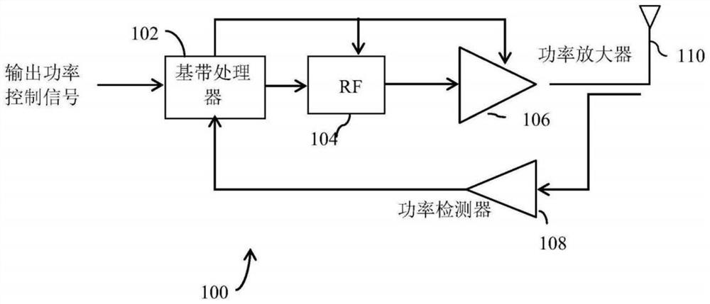
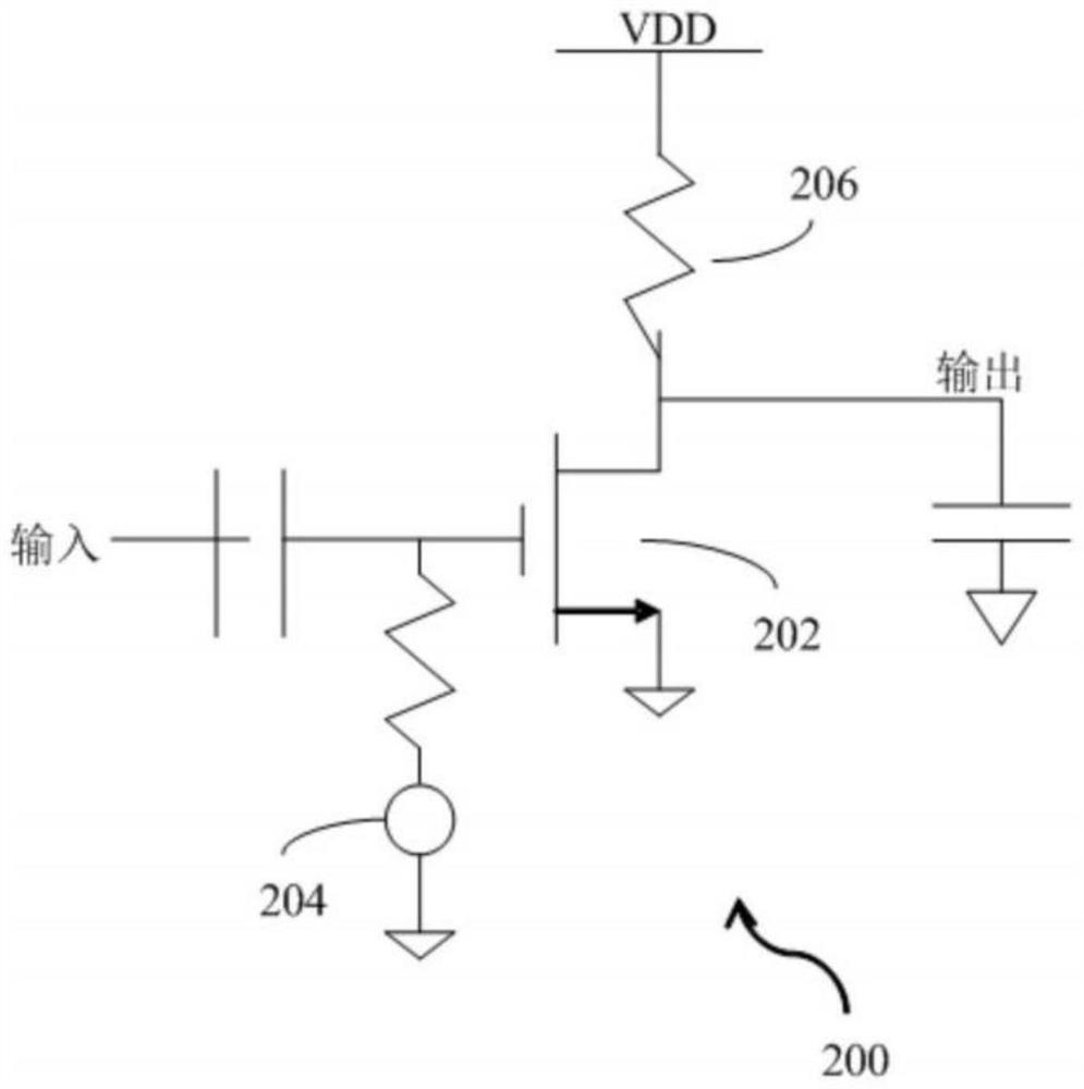
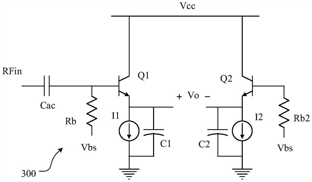
[0046] Hereinafter, the present invention will be described in more detail with reference to the accompanying drawings. In the various figures, identical elements are indicated with similar reference numerals. For the sake of clarity, various parts in the drawings have not been drawn to scale. Also, some well-known parts may not be shown in the drawings.

[0047] In the following, many specific details of the present invention are described, such as device structures, materials, dimensions, processing techniques and techniques, for a clearer understanding of the present invention. However, the invention may be practiced without these specific details, as will be understood by those skilled in the art.

[0048] It should be understood that the connection / coupling of A and B in the embodiment of the present application means that A and B may be connected in series or in parallel, or A and B may be connected through other devices, which is not limited in the embodiment of the p...


PUM


Abstract

The invention discloses a power detector and a radio frequency module. The power detector comprises: an input circuit, the first end of which receives a radio frequency signal, the second end of which is connected to a bias voltage, the input circuit performing voltage division processing based on the radio frequency signal and the bias voltage to generate a plurality of alternating current signals; the multi-branch detection circuit is used for performing power detection on the plurality of alternating current signals to obtain a plurality of detection signals; a summing circuit summing the plurality of detection signals to generate a total detection voltage; and the temperature compensation circuit performs level conversion on the total detection voltage and counteracts temperature deformation to generate output voltage, and the output voltage represents the power of the radio frequency signal. The power detector can adjust the power of the amplified radio frequency signal and generate the output voltage after temperature compensation, so that the accuracy of the power detector is improved.

Description

technical field [0001] The present invention relates to the technical field of electronic circuits, and more specifically, to a power detector and a radio frequency module. Background technique [0002] Radio frequency (Radio Frequency, RF) refers to the electromagnetic frequency that can be radiated into space. The frequency range is roughly between 300KHz and 30GHz, and it is widely used in communication, medicine, plasma detection and other fields. In order to detect the power of the radio frequency in real time, it is usually necessary to supplement it with a power detector to facilitate the control of the transmit power, gain, power consumption and efficiency of the radio frequency front-end link. The power detector generates a voltage signal indicative of the power of the radio frequency signal. A power detector is required to generate a consistent voltage for the same measured RF signal power at different temperatures. [0003] The output of traditional power detect...

Claims


Application Information

Patent Timeline
IPC IPC(8): G01R21/14G01R21/00H04B17/00
CPCG01R21/14G01R21/00H04B17/0085
Inventor 张益诚晋石磊邱仁鍊石秋明
Owner 南京普能通讯科技有限公司
Learn More