High-frequency and high-speed PCB (printed circuit board) copper-clad laminate

A copper-clad laminate, high-speed technology, applied in the direction of printed circuit components, printed circuits, electrical components, etc., can solve problems such as looseness, bulging and bonding, to improve flatness, increase compactness, and reduce gas residual effect

Active Publication Date: 2022-05-03
益阳市明正宏电子有限公司
View PDF6 Cites 0 Cited by
  • Summary
  • Abstract
  • Description
  • Claims
  • Application Information

AI Technical Summary

Problems solved by technology

[0004] In the prior art, when producing copper-clad laminates, when laminating copper foil, the copper foil is directly covered on the substrate, and then the lamination operation is performed. During long-term use and observation, it is found that When there is gas remaining between the copper foil and the substrate between the substrate and the copper foil, after the copper foil is pressed onto the substrate, there will be problems of bulge and loose fit

Method used


Image

  • High-frequency and high-speed PCB (printed circuit board) copper-clad laminate
  • High-frequency and high-speed PCB (printed circuit board) copper-clad laminate
  • High-frequency and high-speed PCB (printed circuit board) copper-clad laminate

Examples


Embodiment 1

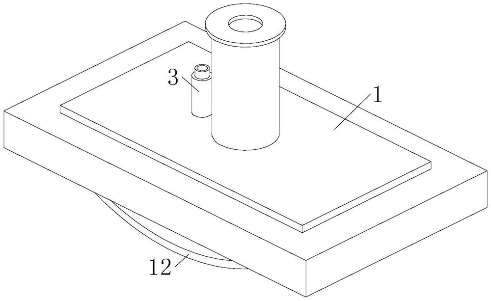
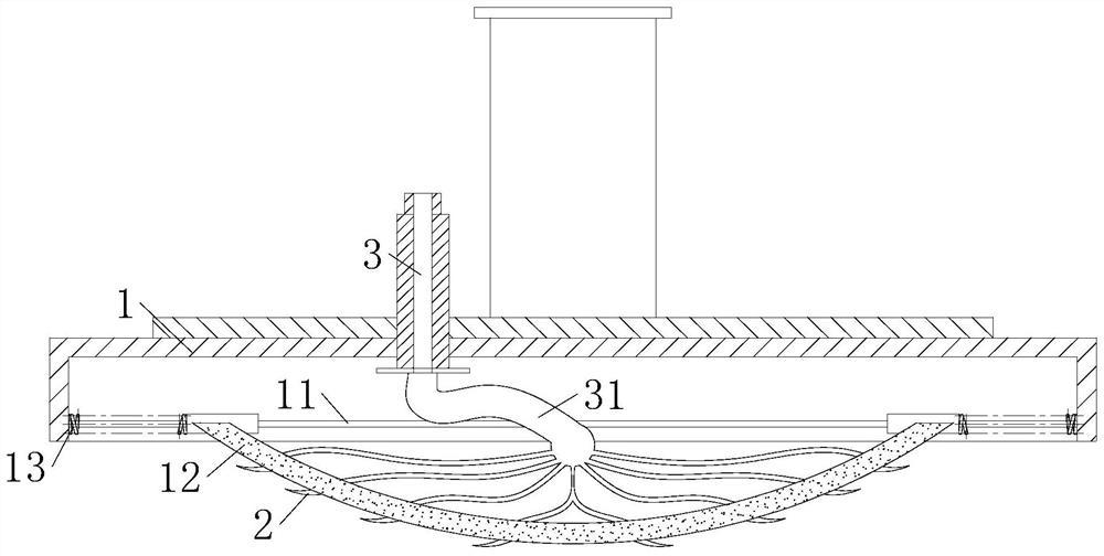
[0028] Such as Figure 1 to Figure 3 As shown, a high-frequency high-speed PCB copper-clad laminate described in the embodiment of the present invention includes a pressing seat 1; a slide bar 11 is fixedly connected to the bottom of the pressing seat 1; 12. Both ends of the elastic pressure plate 12 are slidably connected to the slide bar 11; a spring 13 is installed between the elastic pressure plate 12 and the inner side wall of the pressing seat 1; the middle part of the elastic pressure plate 12 is lower than the two ends; When in use, move the pressing seat 1 to the top of the substrate, and then place the copper foil on the top of the substrate. At this time, the pressing seat 1 can be pressed down, so that the elastic pressing plate 12 can squeeze the copper foil and the substrate. During the pressing process of the copper foil and the substrate, the middle part of the elastic pressing plate 12 will first contact the substrate. During the continuous pressing down of th...

Embodiment 2

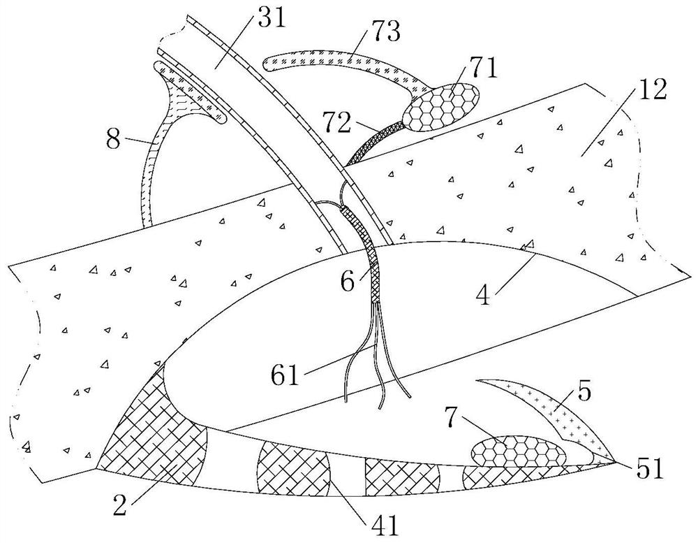
[0038] Such as Figure 4 As shown in Comparative Example 1, another embodiment of the present invention is: multiple sets of protective elastic sheets 91 are provided on both sides of the heating wire 9; connected; by providing protective elastic sheets 91 on both sides of the heating wire 9, the heating wire 9 is supported when there is gas flowing inside the air supply pipe 3, and the heating wire 9 is driven by the air flow, and hits the inside of the air supply pipe 3 The wall causes the problem of affecting the service life of the heating wire 9 and the air supply pipe 3.

[0039] When working, move the pressing seat 1 to the top of the substrate, and then place the copper foil on the top of the substrate. At this time, the pressing seat 1 can be pressed down, so that the elastic pressing plate 12 can squeeze the copper foil and the substrate. During the pressing process of the copper foil and the substrate, the middle part of the elastic pressing plate 12 will first con...


PUM


Abstract

The invention belongs to the technical field of printed circuit board (PCB) manufacturing, and particularly relates to a high-frequency and high-speed PCB copper-clad laminate which comprises a pressing seat. A sliding rod is fixedly connected to the bottom of the pressing seat; an elastic pressing plate is arranged at the bottom of the pressing seat; the two ends of the elastic pressing plate are connected to the sliding rods in a sliding mode. A spring is mounted between the elastic pressing plate and the inner side wall of the pressing seat; the middle part of the elastic pressing plate is lower than the two ends; the arc-shaped elastic pressing plate is arranged at the top of the base plate to press the base plate, gas between the base plate and the copper foil can be extruded out in the pressing process, gas residues between the base plate and the copper foil are reduced, and the tightness degree after the copper foil and the base plate are pressed is improved.

Description

technical field [0001] The invention belongs to the technical field of printed circuit board (PCB) manufacturing, in particular to a high-frequency and high-speed PCB copper-clad laminate. Background technique [0002] Copper-clad laminates are substrates for manufacturing PCBs. The manufacturing process is to impregnate glass fiber cloth, glass fiber felt and other reinforcing materials with adhesives such as epoxy resin and phenolic resin, and dry them at an appropriate temperature to the first stage, and then copper The foil laminate is heated and pressed by a pressing plate to obtain a copper clad laminate. [0003] A Chinese patent with the publication number CN104582238A discloses a PCB board and its manufacturing method, including: an outer layer with at least two detection holes; at least one inner layer arranged between the outer layers, including a test strip and a through back The test strip includes a test hole formed by the back-drilling process and a metal wir...

Claims


Application Information

Patent Timeline
IPC IPC(8): H05K1/02H05K3/02
CPCH05K1/02H05K3/022
Inventor 祝文华吴道新袁国东李显刚陈明灿邬家康
Owner 益阳市明正宏电子有限公司
Why Eureka
Try Eureka