Automatic dispensing and mounting system and method for optical filter

A technology of automatic dispensing and mounting system, applied in the direction of material gluing, devices for coating liquid on the surface, connecting components, etc., which can solve the problem of UV glue offset, affecting the angle of light refraction, uneven thickness of finished filters, etc. question

Active Publication Date: 2022-05-06
中山市联申达科技有限公司
View PDF8 Cites 0 Cited by
  • Summary
  • Abstract
  • Description
  • Claims
  • Application Information

AI Technical Summary

Problems solved by technology

[0005] The purpose of the present invention is to provide a system and method for automatic dispensing and mounting of optical filters, so as to solve the problem of high-efficiency production in the existing production process of dispensing and pasting of optical filters proposed in the above-mentioned background technology. , but in the existing non-standard automation, due to the need to consider the production efficiency, the switching speed between the stations is generally fast, and the circular closed-loop reciprocating processing method is adopted, in which there is a ring between the stations, and the motor The circular position conversion between the driving filters, so that when the filters rotate circularly, especially after the UV glue is applied on the filter base, when the filters are revolving, they are very vulnerable to their own centrifugal force. This leads to the offset phenomenon of UV glue, which leads to the problem of uneven glue between it and the filter substrate when the filter film is attached, which easily leads to uneven thickness of the finished filter, thus Problems that affect the angle of refraction of light

Method used


Image

  • Automatic dispensing and mounting system and method for optical filter
  • Automatic dispensing and mounting system and method for optical filter
  • Automatic dispensing and mounting system and method for optical filter

Examples


Embodiment Construction

[0036] The following will clearly and completely describe the technical solutions in the embodiments of the present invention with reference to the accompanying drawings in the embodiments of the present invention. Obviously, the described embodiments are only some, not all, embodiments of the present invention. Based on the embodiments of the present invention, all other embodiments obtained by persons of ordinary skill in the art without creative efforts fall within the protection scope of the present invention.

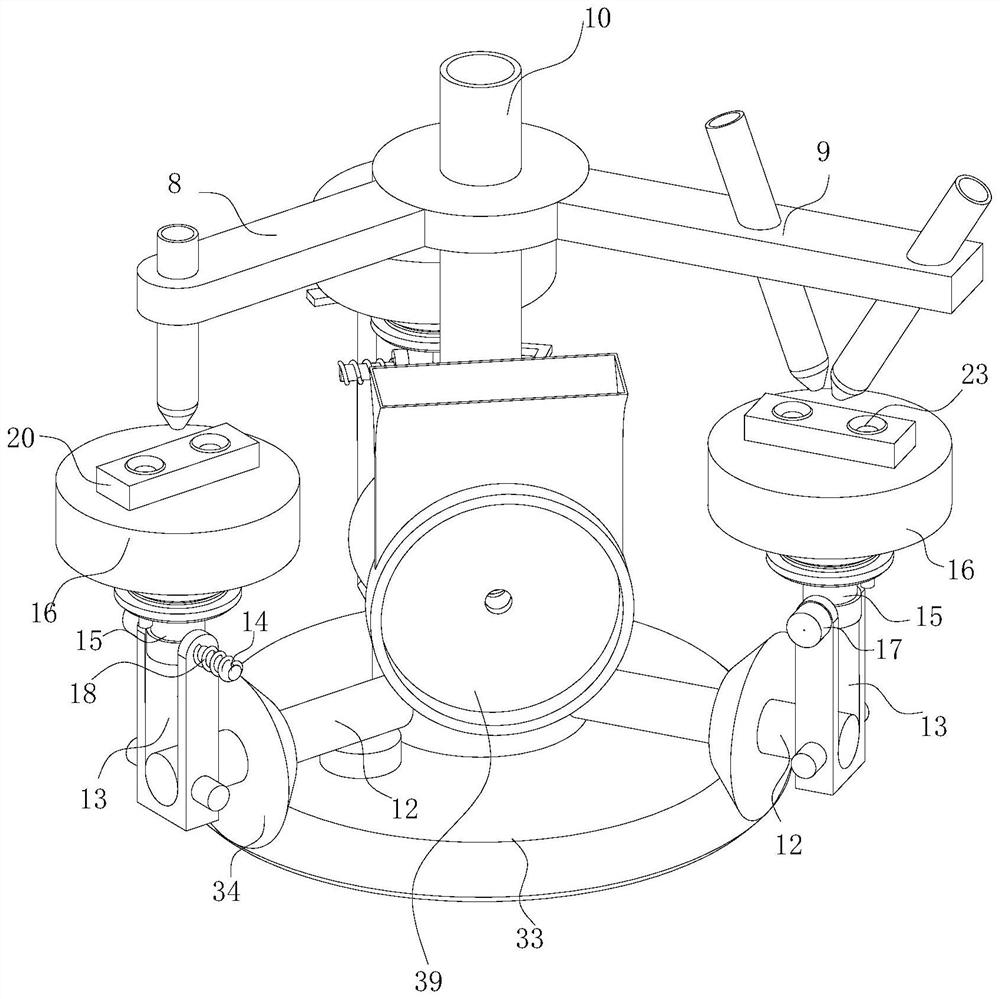
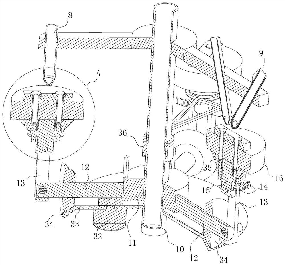
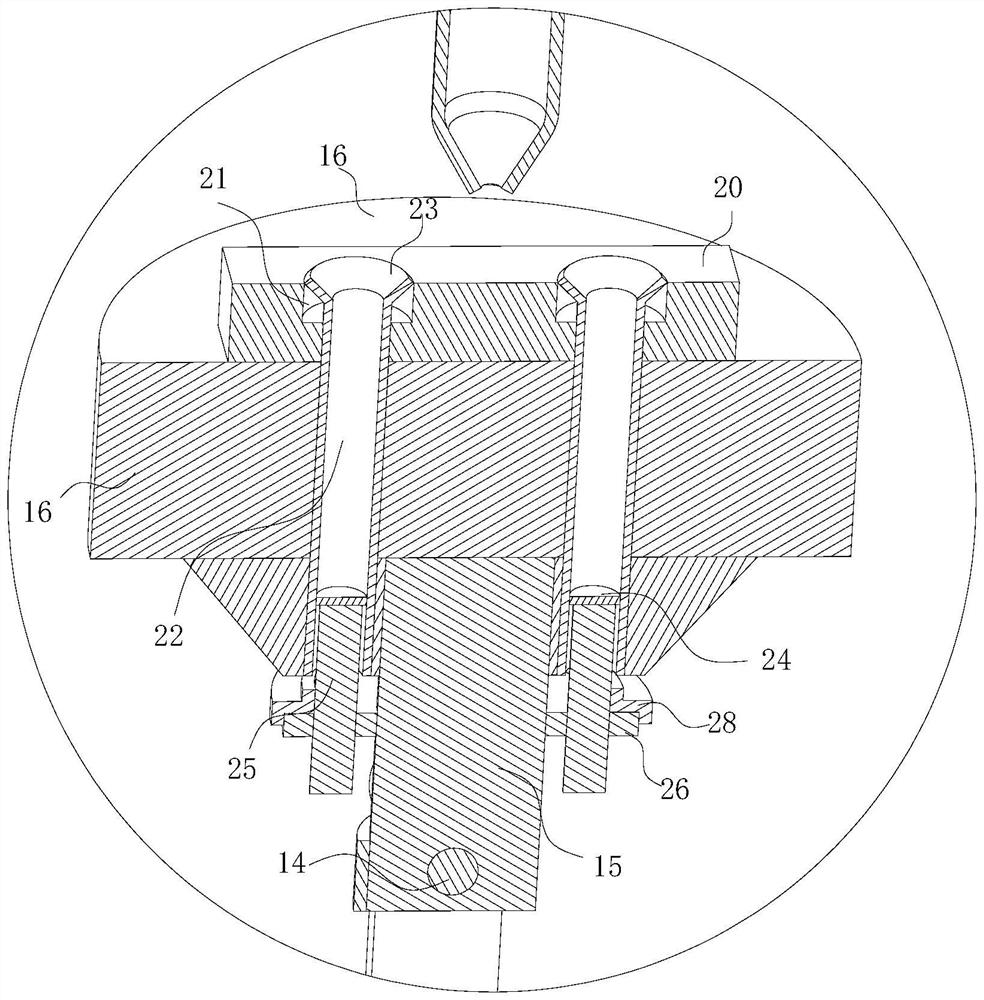
[0037] see Figure 1-8 , the present invention provides a technical solution: an automatic dispensing and mounting system for optical filters, including a dispensing gun 8 for dispensing, a glue coating mechanism 9 for coating glue, and a fixing rod 10. The gun 8 and the glue-wrapping mechanism 9 are respectively fixed on the side wall of the upper end of the fixed rod 10 through a bracket, and the outer wall of the lower end of the fixed rod 10 is rotated to be pr...


PUM


Abstract

The invention discloses an automatic optical filter dispensing and mounting system in the technical field of optical filter dispensing and mounting, which comprises a dispensing gun for dispensing, a glue wrapping mechanism for wrapping glue and a fixing rod, the dispensing gun and the glue wrapping mechanism are fixedly arranged on the side wall of the upper end of the fixing rod through supports, and an orientation plate is rotatably arranged on the outer wall of the lower end of the fixing rod. A plurality of adapter rods are fixedly arranged on the side wall of the azimuth plate around the axis of the azimuth plate in an annular array mode, a vertical U-shaped frame is fixedly arranged at the end, away from the azimuth plate, of each adapter rod, and an angle shaft is rotationally arranged at the upper end of each U-shaped frame; the problem that when an existing optical filter dispensed with UV glue is subjected to station switching revolution, the UV glue deviates due to the fact that the existing optical filter is extremely prone to being subjected to the centrifugal force of the existing optical filter, and consequently the glue between the optical filter and an optical filter base body is not uniform when a filter film is attached later is solved. Therefore, the thickness of the finished optical filter is not uniform, and the light refraction angle is affected.

Description

technical field [0001] The invention relates to the technical field of optical filter dispensing and mounting, in particular to an automatic optical filter dispensing and mounting system and method. Background technique [0002] As the name suggests, the filter has the function of filtering light. In photography creation, the filter plays the role of "seasoning". If you can use filters flexibly, you can improve the performance of photographic works. In black and white photography, filters can be used to change the tone of the scene, making the photos taken closer to nature. In color photography, the use of filters can change the color temperature of the light source, the color of the subject, or have special visual effects; it has the function of filtering light. role. If you can use filters flexibly, you can improve the performance of photographic works. In black and white photography, filters can be used to change the tone of the scene, making the photos taken closer t...

Claims


Application Information

Patent Timeline
Patent Type & Authority Applications(China)
IPC IPC(8): B05C5/02B05C13/02F16B11/00B05D1/26
CPCB05C5/0208B05C13/02F16B11/006B05D1/26
Inventor 梁景
Owner 中山市联申达科技有限公司
Why Eureka
Try Eureka