Pressure salvaging device for pipe tapping falling piece

A salvage device and pipeline technology, which is used in boring/drilling, drilling/drilling equipment, manufacturing tools, etc., can solve the problem that the salvage tool cannot meet the needs of large-scale salvage, cannot meet the needs of salvage of pieces, and the pieces deviate. Hole deviation distance and other problems, to meet the needs of pressure salvage work, a wide range of salvage, and easy operation.

Pending Publication Date: 2022-05-06
RICH HIGH TECH CO LTD
View PDF0 Cites 0 Cited by
  • Summary
  • Abstract
  • Description
  • Claims
  • Application Information

AI Technical Summary

Problems solved by technology

[0003] At present, there are two main salvage methods for perforating and falling pieces in the pipeline. One is the stop-loss salvage process. This method is: empty the pipeline and manually remove the falling pieces by construction workers. In normal transportation, there will be oil and gas leakage, which will pollute the environment and bring large economic losses
The other is the non-stop fishing process. This method currently has the problem that the fishing tools cannot meet the needs of large-scale fishing.
[0004] In the pipeline drilling operation, the size of the falling piece is basically the same as the size of the opening, and it is necessary to accurately find the center position of the falling piece to remove it from the opening; however, due to the impact of the air flow or liquid flow in the pipeline, the The falling pieces deviate from the hole and the deviation distance is not fixed, while the existing falling piece fishing device can only fish in a small area within the center of the hole, which cannot meet the salvage requirements of the falling pieces that deviate from the hole

Method used


Image

  • Pressure salvaging device for pipe tapping falling piece
  • Pressure salvaging device for pipe tapping falling piece
  • Pressure salvaging device for pipe tapping falling piece

Examples


Embodiment Construction

[0044] The embodiments of the present invention will be described in detail below in conjunction with the accompanying drawings. This embodiment is implemented on the premise of the technical solution of the present invention, and detailed implementation methods and specific operating procedures are provided, but the scope of protection of the present invention is not limited to the following Described embodiment.

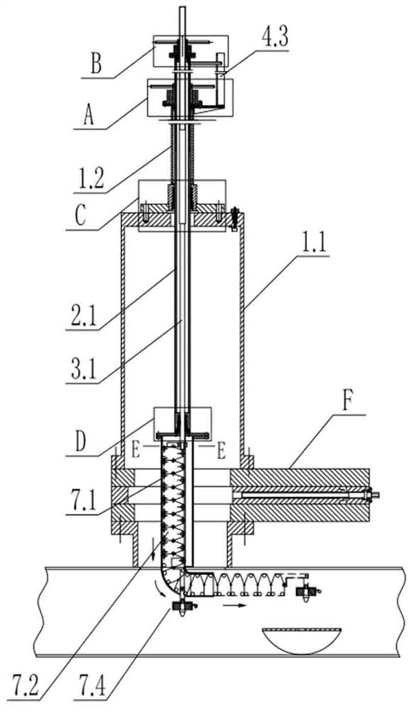
[0045] Such as figure 1 As shown, the pipeline opening and falling pieces under pressure fishing device of the present invention includes

[0046] The sealing structure is arranged on the connecting flange at the opening of the pipeline. The sealing structure has a sealing shell 1.1 extending upward from the connecting flange and a support sleeve 1.2 sealed and arranged on the top of the sealing shell 1.1. The sealing shell 1.1 and the pipeline form a The anti-escape chamber that prevents the escape of oil and gas in the pipeline can not only ensure the normal tra...


PUM


Abstract

The invention discloses a pipeline tapping falling piece under-pressure fishing device which comprises a sealing structure provided with a sealing shell and a supporting sleeve. The first lifting mechanism is provided with a first pull rod; the second lifting mechanism is provided with a second pull rod; the salvage structure is provided with a guide part and a salvage assembly, the guide part is arranged at the bottom of the first pull rod, the top of the salvage assembly is fixed to the bottom of the second pull rod, and the salvage assembly slides along the guide part and has a first salvage state and a second salvage state; in the first fishing state, the fishing assembly is in a vertical state and vertically coincides with the center of the pipeline opening; and in the second salvage state, the tail end of the salvage assembly is horizontally bent and horizontally extends to the downstream. The sealing shell is fixed to the sandwich valve to define the anti-escape cavity, and the requirement for under-pressure fishing work can be met; the salvage position of the salvage assembly can be adjusted at will, the salvage range is wide, the salvage requirements of different salvage positions are met, and the defect that a traditional salvage device can only conduct salvage in a small range is overcome.

Description

technical field [0001] The invention relates to the field of pipeline drilling, in particular to a fishing device for pipeline drilling and falling pieces under pressure. Background technique [0002] During the process of pipe drilling, a saddle-shaped falling piece will be produced when the drilling barrel cutter cuts the hole. Although the anti-falling device is provided on the center drill of the barrel cutter, it cannot be used under some extreme conditions (such as anti-dropping device failure) there is still the risk of the falling pieces falling into the running pipeline. If the falling pieces are not salvaged in time, it will bring great trouble to the pipeline cleaning and internal inspection described later. [0003] At present, there are two main salvage methods for perforating and falling pieces in the pipeline. One is the stop-loss salvage process. This method is: empty the pipeline and manually remove the falling pieces by construction workers. In normal tran...

Claims


Application Information

Patent Timeline
IPC IPC(8): B23B41/08B23B47/00
CPCB23B41/00B23B47/00
Inventor 徐兴斌宋彩振徐昕张瀚元许俊杰郭俊华黄利峰郝学坤王增产刘宗波
Owner RICH HIGH TECH CO LTD
Why Eureka
Try Eureka