Variable-speed sawing control system of sawing machine

A control system and sawing technology, applied in the field of sawing machines, can solve the problems that the fatigue life of the sawing device affects the cutting efficiency, the speed cannot be adjusted, and the cutting position cannot be adjusted, etc., so as to improve the convenience of control, convenient position adjustment, Cut fine and perfect effect

Pending Publication Date: 2022-05-06
缙云县澳美逊计算机系统工程有限公司
View PDF1 Cites 0 Cited by
  • Summary
  • Abstract
  • Description
  • Claims
  • Application Information

AI Technical Summary

Problems solved by technology

[0004] The object of the present invention is to provide a sawing machine variable speed sawing control system to solve the problem that the existing sawing machine variable speed sawing control system proposed in the above background technology cannot perform related speed regulation during the related processing and cutting operations during use. And the relevant cutting position cannot be adjusted, thus affecting the fatigue life of the sawing device and related cutting efficiency problems

Method used


Image

  • Variable-speed sawing control system of sawing machine
  • Variable-speed sawing control system of sawing machine
  • Variable-speed sawing control system of sawing machine

Examples


Embodiment 1

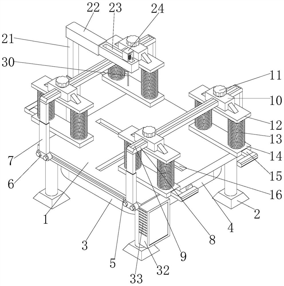
[0026] see also Figure 1-6 The invention provides a technical scheme: the variable-speed sawing control system of the sawing machine comprises a workbench 1, the bottom of the workbench 1 is fixedly installed with a connecting box body 3, both sides of the workbench 1 are provided with a first sliding groove 5, the interior of the first sliding groove 5 is movably installed with a first sliding block 6, the top of the first sliding block 6 is fixedly installed with a first telescopic rod 7, and the top of the first telescopic rod 7 is fixedly installed with a fixed rod 8, The inner part of the fixed rod 8 is provided with a second sliding groove 9, the outer part of the second sliding groove 9 is movably installed with a second sliding block 10, the top of the second sliding block 10 is movably installed with an adjusting and fixing knob 11, the bottom of the second sliding block 10 is fixedly installed with a first connecting plate 12, the bottom of the first connecting plate 12 ...

Embodiment 2

[0029] see also Figure 1-6 In the first embodiment of the invention, the size of the connecting piece 14 is matched with the size of the sliding piece, and in the second embodiment, the size of the connecting piece 14 is matched with the size of the sliding piece. A support base 2 is fixedly installed at the bottom of the workbench 1, a connecting slot is arranged on one side of the connecting box body 3, a collection drawer 4 is movably installed inside the connecting slot, and a cutting slot 16 is arranged at the top of the workbench 1. A control box 32 is fixedly installed on the front of the workbench 1, and heat dissipation holes 33 are arranged on both sides of the control box 32.

[0030] In this embodiment, the second connecting plate 14 is fixedly installed through the bottom of the elastic member 13, in which one end of the second connecting plate 14 is internally provided with a connecting groove, and the interior of the connecting groove is fixedly installed with a tel...

Embodiment 3

[0032] as Figure 1-6 As shown in the figure, on the basis of embodiment 1 and embodiment 2, the invention provides a technical scheme: the bottom of the connecting box body 3 is fixedly installed with a mounting block 17, the bottom of the mounting block 17 is movably installed with a rotating shaft 18, the bottom of the rotating shaft 18 is fixedly installed with a fixing block 19, one side of the rotating shaft 18 is fixedly installed with a connecting rod 20, and the end of the connecting rod 20 is fixedly installed with a second telescopic rod 21, The top of the second telescopic rod 21 is fixedly installed with the third telescopic rod 21, the end of the second telescopic rod 22 is provided with a third sliding groove 23, and the top of the third sliding groove 23 is movably installed with a cutting mechanism 24.

[0033]In this embodiment, a mounting block 17 is fixedly installed at the bottom of the connecting box body 3 to facilitate the relevant connection operation with ...


PUM


Abstract

The invention discloses a sawing machine variable-speed sawing control system which comprises a workbench, first sliding grooves are formed in the two sides of the workbench, first sliding blocks are movably installed in the first sliding grooves, first telescopic rod pieces are fixedly installed at the tops of the first sliding blocks, and fixed rod pieces are fixedly installed at the tops of the first telescopic rod pieces; and a second sliding groove is formed in the fixing rod piece, a second sliding block is movably installed outside the second sliding groove, an adjusting fixing rotary knob is movably installed at the top of the second sliding block, and a first connecting plate piece is fixedly installed at the bottom of the second sliding block. According to the plate cutting device, the height of the related fixing mechanism and the height of the related cutting mechanism are conveniently adjusted through the arrangement of the related telescopic rod pieces, so that different cutting modes can be conducted on different plates during related cutting operation, and overall cutting is finer by adjusting the related cutting height.

Description

technical field [0001] The invention belongs to the technical field of sawing machines, in particular to a variable speed sawing control system of sawing machines. Background technology [0002] The servo position control module of the sawing machine system adopts the position control of the combination of sampling interpolation and preview control. Due to the electromagnetic mechanical lag and motion inertia, it is almost impossible to control the feeding slide to move 0.1mm through "on" and "off". In order to ensure the minimum feeding length and feeding accuracy, the rear clamp moves the feeding slide back to LK position, and then moves forward to the predicted position lt to close the feeding solenoid valve. When the movement of the feeding cylinder stops, the rear pliers clamp tightly. Sawing machine is a relatively simple machine tool. Users will not require their own sawing machine to have the function of machining center. The computer-controlled sawing machine not only im...

Claims


Application Information

Patent Timeline
Patent Type & Authority Applications(China)
IPC IPC(8): B23D51/00B23D51/16B23D59/00
CPCB23D51/16B23D51/00B23D59/001
Inventor 赵挺伊
Owner 缙云县澳美逊计算机系统工程有限公司
Why Eureka
Try Eureka