Steel structure support used for ship web and provided with anti-corrosion structure for buffering and damping
A technology of steel structure and steel bracket, applied in the direction of spring/shock absorber, hull, ship construction, etc., can solve the problems of low protection, poor shock absorption performance of wire harness, inconvenient wire harness disassembly, etc., to prolong service life and reduce Friction, the effect of improving mounting stability
- Summary
- Abstract
- Description
- Claims
- Application Information
AI Technical Summary
Problems solved by technology
Method used
Image
Examples
Embodiment 1
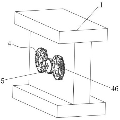
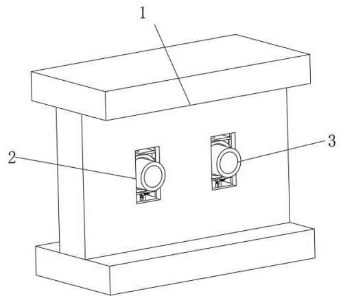
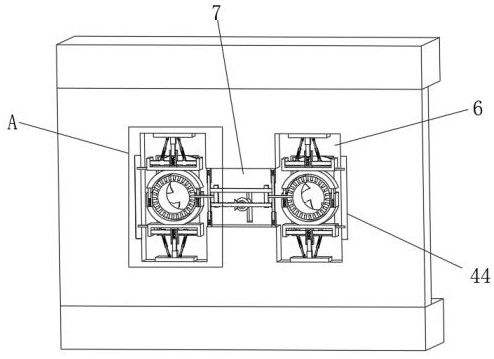
[0035] Embodiment one, by Figure 1 to Figure 8 Given, the present invention includes a steel bracket body 1, one side of the steel bracket body 1 is symmetrically provided with two installation grooves 2, through the design of the wire insertion tube 3, it is convenient to install the wire harness, and at the same time, the installation efficiency of the wire harness is improved , first pass the wiring harness through the wire insertion tube 3, and then install the wire insertion tube 3 and the installation groove 2, avoid directly passing the wire harness through the installation groove 2 to realize the installation of the wire harness and the steel bracket body 1, and effectively solve the problem of the steel bracket body 1 When the size is deep, the wiring harness is easy to bend and the installation speed of the wiring harness is slow. The inside of the two installation grooves 2 is inserted with the insertion tube 3, and one end of the two insertion tubes 3 is connected ...
Embodiment 2
[0038] Embodiment two, on the basis of embodiment one, by image 3 with Figure 4 Given, the outer wall of the insertion tube 3 is equidistantly provided with insertion holes 15, wherein the two clamping cylinders 11 adjacent to the first receiving groove 6 are provided with first slots 16, wherein The two first plug-in rods 12 of 6 are provided with second slots 17, and the fastening group includes two connecting parts, a slide rod 20, a two-way screw rod 21, a movable plate 22, and a second plug-in rod 23 and the first bevel gear 24, the inside of the second accommodation groove 7 is provided with a slide bar 20, the bottom of the slide bar 20 is provided with a two-way screw mandrel 21, and the middle position of the two-way screw mandrel 21 is provided with a first bevel gear 24, two-way Threaded movable plates 22 are symmetrically arranged on the screw rod 21, and the two movable plates 22 are slidably connected with the slide bar 20. The middle positions of the two mova...
Embodiment 3
[0040] Embodiment three, on the basis of embodiment one, by image 3 with Figure 4 It is given that the connecting parts each include two fixed cylinders 18 and two movable insertion rods 19, the fixed cylinders 18 are symmetrically installed on the top and bottom ends of the second receiving groove 7, and between the interiors of the two adjacent fixed cylinders 18 in the longitudinal direction It should be noted here that the fixed cylinder 18 and the movable plunger 19 can be elastically connected by a spring, and both ends of the slide rod 20 and the two-way screw rod 21 are connected with the movable plunger 19. And the second insertion rod 23 runs through the inside of the movable insertion rod 19;
[0041] After the second insertion rod 23 penetrates through the movable insertion rod 19, the connection between the second insertion rod 23 and the movable insertion rod 19 can be realized, thereby facilitating the tight connection between the fastening group and the inse...
PUM
 Abstract
Description
Claims
Application Information
 - R&D
- Intellectual Property
- Life Sciences
- Materials
- Tech Scout
- Unparalleled Data Quality
- Higher Quality Content
- 60% Fewer Hallucinations
Browse by: Latest US Patents, China's latest patents, Technical Efficacy Thesaurus, Application Domain, Technology Topic, Popular Technical Reports.
© 2025 PatSnap. All rights reserved.Legal|Privacy policy|Modern Slavery Act Transparency Statement|Sitemap|About US| Contact US: help@patsnap.com


