
Eureka
For R&D, Eureka makes reading and utilizing patents & technical documents easy.
Eureka AIR
Designed for self-driven R&D workflows. Generate viable solutions, solve complex R&D challenges, empower your innovation with AI.

Eureka Materials
Designed for material experts only. Revolutionize your material R&D, from search, analyze, to developing new materials.

TechResearch
Generate reliable direction feasibility study reports for your R&D in just a few steps.

TechSeek
Discover and master advanced knowledge NOW. Basics, ideas, possibilities, all at once.

TechMind
As an expert in R&D Theories, TechMind can generates customized viable solutions instantly.

TechRisk
Analyze your overall solution with one click, know your potential R&D risks in advance.

TechMonitor
Get weekly tech updates, stay abreast of the latest tech innovations and key insights.
Gravimetric method gas adsorption testing device
A technology of gas adsorption and testing equipment, applied in the direction of using material absorption and weighing, etc., can solve the problem of low pressure, achieve the effect of shortening the test time and improving the test efficiency
- Summary
- Abstract
- Description
- Claims
- Application Information
AI Technical Summary
Problems solved by technology
Method used
Image

Examples
Embodiment 1
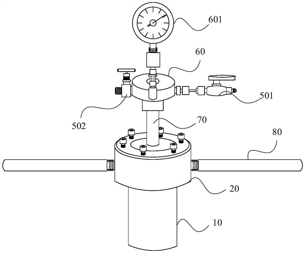
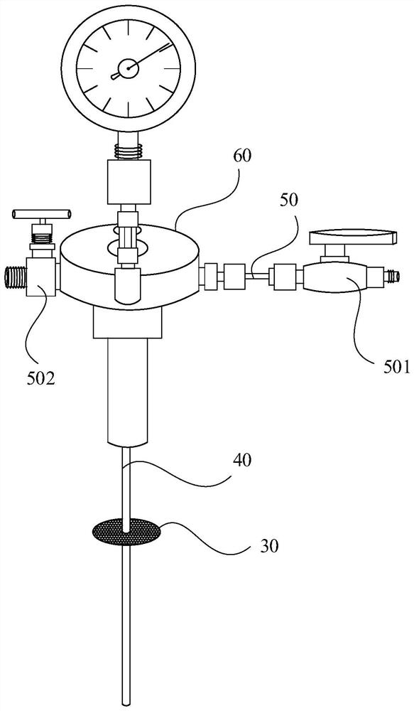
[0051] This embodiment discloses a gravimetric gas adsorption test device, such as Figure 1-3 As shown, it includes a detection component, one end of the detection component has an inlet, and the detection component has a closed sample holding chamber, the sample holding chamber is used to place the sample to be tested, and the inlet is connected to the sample holding chamber cavity, the detection component is provided with a filter membrane, and the filter membrane is located between the inlet and the sample to be tested.
[0052] In this embodiment, the sample holding chamber is set to be airtight, and the test device can withstand a pressure of up to 200 Bar; by setting a filter membrane in the sample holding chamber, the sample to be tested is always in a stable and clean space, preventing the The sample to be tested is blown away by the high-pressure airflow during the air and air intake process. The test device is capable of high-pressure gas adsorption test, and compa...
Embodiment 2
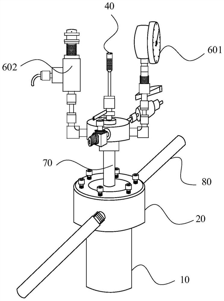
[0067] refer to Figure 4 It should be understood that the sample compartment 10 of the gravimetric gas adsorption testing device of this embodiment is a hollow and elongated cylindrical structure, the interior of the sample compartment 10 forms a sample holding chamber, and the inlet is located on the left side of the sample holding chamber. By adopting the above-mentioned structural form, the effective volume of the sample holding chamber is greatly increased under the condition that the outer surface area is as small as possible.
[0068] There is a VCR joint 503 at the inlet, and the filter membrane is set inside the VCR joint 503, wherein the filter membrane is set inside the VCR joint 503, which can prevent the light sample to be tested from being brought to the position of other parts by the airflow during the inflation process Contaminate and affect test results.
[0069] The gravimetric gas adsorption testing device also includes a four-way joint 90, the first end of...
PUM
 Abstract
Description
Claims
Application Information
 - R&D Engineer
- R&D Manager
- IP Professional
- Industry Leading Data Capabilities
- Powerful AI technology
- Patent DNA Extraction
Browse by: Latest US Patents, China's latest patents, Technical Efficacy Thesaurus, Application Domain, Technology Topic, Popular Technical Reports.
© 2024 PatSnap. All rights reserved.Legal|Privacy policy|Modern Slavery Act Transparency Statement|Sitemap|About US| Contact US: help@patsnap.com