
Common mode choke detection system and working method thereof

A common-mode inductance and detection system technology, which is applied in the direction of measuring devices, measuring electrical variables, measuring device casings, etc., to achieve the effects of avoiding falling off, short time consumption, and increasing stability

Pending Publication Date: 2022-05-06
安徽龙磁新能源技术有限公司
View PDF1 Cites 0 Cited by
  • Summary
  • Abstract
  • Description
  • Claims
  • Application Information

AI Technical Summary

Problems solved by technology

[0004] The purpose of the present invention is to provide a common-mode inductance detection system and its working method. Through the test mechanism, the four magnetic ring pins on the common-mode inductance enter into the corresponding pin holes respectively, and the bottom surface of the mounting plate and the top of the suction cup The surface fit increases the stability of the common mode inductance and the test frame during installation. The linear cylinder pushes the top plate upward and drives the test probe. The test probe is connected to the pins of the magnetic ring, and the resistance data is transmitted to the digital display through the signal line. In the resistance meter, the performance of the common-mode inductor can be judged. The whole test process is fast and time-consuming, and does not require too much manual intervention, which improves the test efficiency of the common-mode inductor and solves the problems mentioned in the above-mentioned background technology.

Method used


Image

  • Common mode choke detection system and working method thereof
  • Common mode choke detection system and working method thereof
  • Common mode choke detection system and working method thereof

Examples


Embodiment Construction

[0028] In order to further explain the technical means and effects of the present invention to achieve the intended purpose of the invention, the specific implementation, structure, features and effects of the present invention will be described in detail below in conjunction with the accompanying drawings and preferred embodiments.

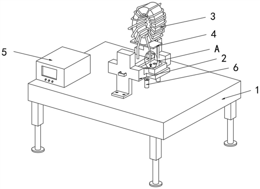
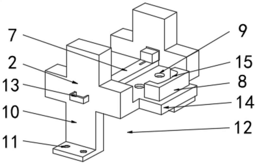
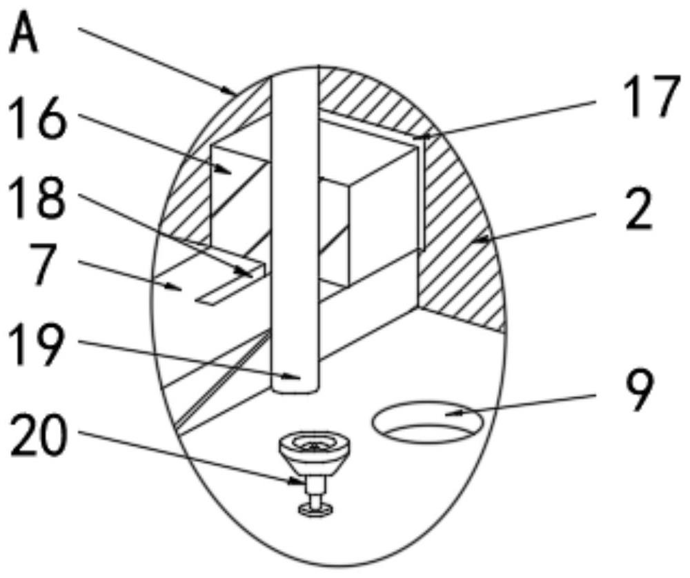
[0029] see figure 1 , figure 2 , image 3 and Figure 5 As shown, the present invention provides a common-mode inductance detection system, including a test bench 1, a test frame 2 is installed on the top surface of the test bench 1, a common-mode inductor 3 is placed inside the test frame 2, and the bottom surface of the common-mode inductor 3 is connected to There is a mounting plate 4, and a coil is wound on the surface of the common mode inductor 3, and the bottom surface of the coil is provided with a magnetic ring pin 19. The material of the mounting plate 4 is an epoxy board, and a testing mechanism is provided on the surface of the tes...


PUM


Abstract

The invention discloses a common-mode inductor detection system and a working method thereof, and particularly relates to the technical field of common-mode inductor detection.The common-mode inductor detection system comprises a test board, a test frame is installed on the top face of the test board, and a common-mode inductor is placed in the test frame; according to the invention, through the test mechanism, four magnetic ring pins on the common mode inductor enter corresponding pin holes respectively, the bottom surface of the mounting plate is attached to the top surface of the suction cup, the stability of the common mode inductor and the test frame during mounting is improved, two elastic cushion blocks are close to each other, the two surfaces of the common mode inductor can be clamped and fixed conveniently, and the test efficiency is improved. The linear air cylinder pushes the top plate to be upward and drives the test probe to sleeve the magnetic ring pin, resistance data is transmitted to the digital display resistance instrument through the signal line, then the performance of the common mode inductor can be judged, the whole test process is fast, consumed time is short, excessive manual intervention is not needed, and the test efficiency is improved. And the test efficiency of the common mode choke is improved.

Description

technical field [0001] The invention relates to the technical field of common-mode inductance detection, in particular to a common-mode inductance detection system and a working method thereof. Background technique [0002] Common-mode inductors are also called common-mode choke coils, which are often used in switching power supplies of computers to filter common-mode electromagnetic interference signals. Electromagnetic waves are radiated outward. The common mode inductor is composed of a coil and an iron core. During the production process, two coils need to be wound on the iron core in a specific direction. [0003] A common-mode inductor electric strength detection device with the publication number CN211577298U uses hydraulic push rods on both sides to push the bearing plates of the two countries to move relative to each other, and uses four test shrapnels to contact the pins of the common-mode inductor to measure the dielectric strength of the common-mode inductor. De...

Claims


Application Information

Patent Timeline
Patent Type & Authority Applications(China)
IPC IPC(8): G01R27/02G01R1/04
CPCG01R27/02G01R1/04
Inventor 李兵徐兵何小康
Owner 安徽龙磁新能源技术有限公司
Learn More