
True surface velocity fusion modeling method for double complex regions

A technology of velocity fusion and modeling method, applied in seismology, seismic signal processing, geophysical measurement, etc., it can solve the problems of inappropriate selection of depth range, reduced accuracy of velocity, and no consideration of undulating elevation difference. performance and promotion of application, improve quality and effect, improve the effect of imaging

Pending Publication Date: 2022-05-06
CHINA PETROLEUM & CHEM CORP +1
View PDF2 Cites 0 Cited by
  • Summary
  • Abstract
  • Description
  • Claims
  • Application Information

AI Technical Summary

Problems solved by technology

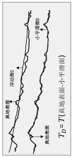
This patent mainly introduces the algorithm of how to fuse the velocity values ​​of the near-surface and middle-deep layers, which has achieved a good processing effect overall, but there are still several problems that need to be further solved: (1) For step 1, using the first arrival layer of the cannon The near-surface velocity obtained by analytical inversion is on the undulating elevation surface (true surface), and the reflected wave tomographic velocity is on the surface (floating surface) smoothed with a larger radius on the undulating elevation surface. The difference between the two surfaces is large. Big
(2) In step 1, the velocity model of the tomographic inversion of the first arrival of the cannon is limited by the ray density. Starting from the surface, as the depth increases, the accuracy of the velocity decreases significantly below the depth of the bottom interface covered by the ray density. Improper choice of depth range has a great impact on speed fusion
(3) In step 2, the algorithm for the fusion process of the near-surface and mid-deep velocity values ​​is relatively cumbersome, and the geophysical meaning is not very clear
This invention patent is mainly aimed at the seismic data in the east, and does not consider the existence of undulating elevation differences. This method is not suitable for the complex seismic data in the west

Method used


Image

  • True surface velocity fusion modeling method for double complex regions
  • True surface velocity fusion modeling method for double complex regions
  • True surface velocity fusion modeling method for double complex regions

Examples


Embodiment Construction

[0032] It should be noted that the following detailed description is exemplary and intended to provide further explanation of the present invention. Unless defined otherwise, all technical and scientific terms used herein have the same meaning as commonly understood by one of ordinary skill in the art to which this invention belongs.

[0033] It should be noted that the terminology used here is only for describing specific embodiments, and is not intended to limit exemplary embodiments according to the present invention. As used herein, unless the context clearly dictates otherwise, the singular is intended to include the plural, and it should also be understood that when the terms "comprising" and / or "comprising" are used in this specification, they mean There are features, steps, operations and / or combinations thereof.

[0034] The true surface velocity fusion modeling method in the double complex area of ​​the present invention comprises the following steps:

[0035] Step...


PUM


Abstract

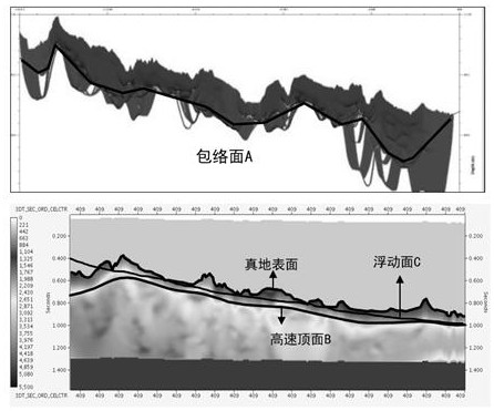
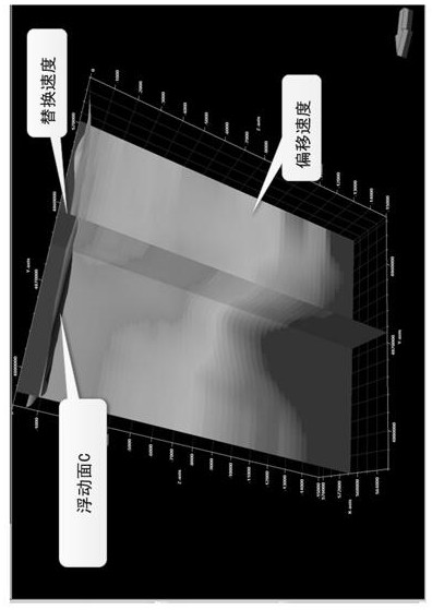
The invention provides a real surface velocity fusion modeling method for double complex regions. The real surface velocity fusion modeling method for the double complex regions comprises the following steps: step 1, determining a depth credible range of a near-surface model; 2, solving a high-speed top interface and a floating reference surface; step 3, calculating a floating reference surface correction value and correcting seismic data; step 4, carrying out mid-deep layer reflected wave velocity analysis and chromatographic modeling; step 5, unification and speed trend analysis of a true surface speed fusion initial surface are carried out; step 6, velocity gradient correction and inverse distance weighted fusion modeling are carried out; and step 7, outputting the seismic data and the fused true surface velocity model. According to the real surface velocity fusion modeling method for the double complex regions, the defect of insufficient precision of a near surface layer of reflection tomography modeling can be effectively overcome, the pre-stack depth migration velocity modeling precision is improved, the migration imaging quality is improved, and well seismic errors are reduced.

Description

technical field [0001] The invention relates to the technical field of oil field development, in particular to a true surface velocity fusion modeling method in double complex areas. Background technique [0002] With the gradual development of pre-stack depth migration technology in major oilfields, a good processing effect has been achieved overall. Seismic data in the piedmont of western China have low signal-to-noise ratio, poor consistency, and severe lateral velocity variation, sometimes accompanied by velocity reversal. Pre-depth migration is difficult to achieve the desired results. Therefore, how to establish a true surface velocity model and improve the accuracy of prestack depth migration velocity modeling has become the key to solving the migration imaging quality of complex piedmont data. [0003] Aiming at the problem of velocity modeling in this type of area, many scholars have done research, mainly including: the medium velocity structure of the surface lay...

Claims


Application Information

Patent Timeline
Patent Type & Authority Applications(China)
IPC IPC(8): G01V1/36
CPCG01V1/36G01V1/282G01V2210/512G01V2210/66
Inventor 滕厚华李继光赵胜天吴常玉王锋刘鹏翔马晓义
Owner CHINA PETROLEUM & CHEM CORP
Learn More