
Pattern distortion compensation method and photoetching exposure method

A technology of pattern distortion and compensation method, which is applied to microlithography exposure equipment, photoengraving process of pattern surface, photoengraving process exposure device, etc., and can solve the problems of pattern distortion and image distortion.

Pending Publication Date: 2022-05-06
INST OF MICROELECTRONICS CHINESE ACAD OF SCI +1
View PDF0 Cites 0 Cited by
  • Summary
  • Abstract
  • Description
  • Claims
  • Application Information

AI Technical Summary

Problems solved by technology

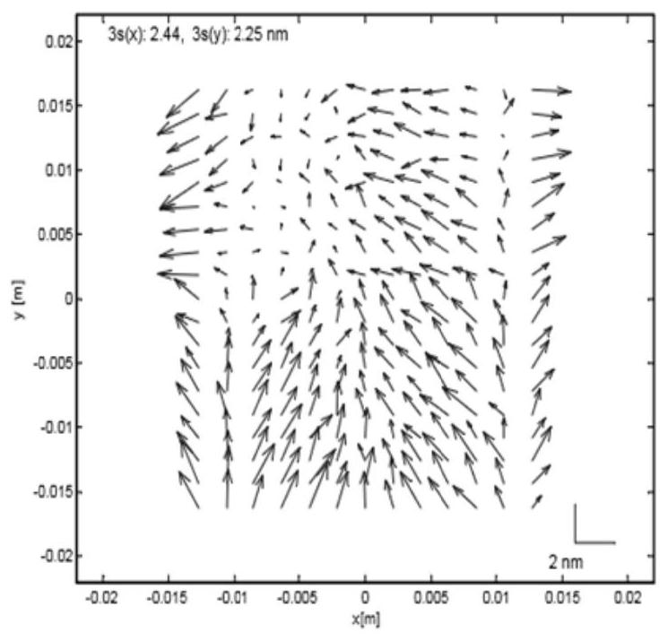
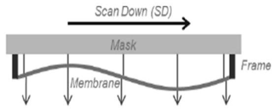
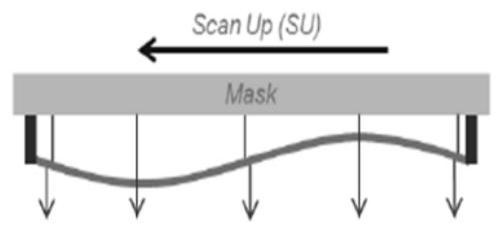
For this reason, the application proposes a compensation method for graphic distortion and a method for lithographic exposure to solve the problem of image distortion caused by the protective film

Method used


Image

  • Pattern distortion compensation method and photoetching exposure method
  • Pattern distortion compensation method and photoetching exposure method
  • Pattern distortion compensation method and photoetching exposure method

Examples


Embodiment Construction

[0017] Hereinafter, embodiments of the present disclosure will be described with reference to the drawings. It should be understood, however, that these descriptions are exemplary only, and are not intended to limit the scope of the present disclosure. Also, in the following description, descriptions of well-known structures and techniques are omitted to avoid unnecessarily obscuring the concepts of the present disclosure.

[0018] Various structural schematic diagrams according to embodiments of the present disclosure are shown in the accompanying drawings. The figures are not drawn to scale, with certain details exaggerated and possibly omitted for clarity of presentation. The shapes of the various regions and layers shown in the figure, as well as their relative sizes and positional relationships are only exemplary, and may deviate due to manufacturing tolerances or technical limitations in practice, and those skilled in the art will Regions / layers with different shapes, ...


PUM


Abstract

The invention relates to the field of semiconductor manufacturing, in particular to a graphic distortion compensation method and a photoetching exposure method, graphic distortion is caused by installing a protective film on a mask, and the graphic distortion compensation method comprises the following steps: measuring a first graphic feature generated by the mask on which the protective film is installed; measuring a second graphic feature generated by the mask without the protective film; establishing a graph distortion model based on the difference between the first graph feature and the second graph feature; and calculating the compensation amount according to the graph distortion model. According to the embodiment of the invention, errors caused by various conditions can be automatically compensated, pattern distortion caused by the protective film under various conditions can be predicted, and the accuracy and efficiency of pattern distortion compensation are improved.

Description

technical field [0001] The present application relates to the field of semiconductor manufacturing, and in particular to a method for compensating pattern distortion and a photolithography exposure method. Background technique [0002] A lithographic apparatus is an apparatus that transfers a desired pattern onto a substrate. A lithographic apparatus may be used, for example, in the manufacture of integrated circuits (ICs). In this case, the design pattern is first processed on the template, such as a mask (MASK or RETICLE), which can be used to generate a circuit pattern corresponding to a single layer of the IC, which can be imaged on the coated radiation-sensitive material (resist). agent) layer of substrates (such as silicon wafers). Typically, a single wafer will contain an entire grid of repeating units exposed in succession. Known lithographic apparatuses include so-called steppers, which expose the entire pattern on the substrate at once, and known lithographic ap...

Claims


Application Information

Patent Timeline
Patent Type & Authority Applications(China)
IPC IPC(8): G03F1/48G03F1/44G03F7/20
CPCG03F1/48G03F1/44G03F7/20
Inventor 田范焕梁时元贺晓彬刘金彪杨涛李亭亭
Owner INST OF MICROELECTRONICS CHINESE ACAD OF SCI
Learn More