
Constant-voltage constant-current wireless power transmission device based on three coils

A wireless power transmission, constant current technology, applied in circuit devices, output power conversion devices, irreversible AC power input into DC power output, etc. Problems such as switchable to mode and inability to achieve load constant current or constant voltage output at the same time

Pending Publication Date: 2022-05-06
XIAMEN UNIV
View PDF0 Cites 0 Cited by
  • Summary
  • Abstract
  • Description
  • Claims
  • Application Information

AI Technical Summary

Problems solved by technology

At the same time, when the system load changes, the traditional resonant compensation network cannot realize the load constant current or constant voltage output at the same time. It is often only designed for one constant voltage mode or constant current mode, and the mode cannot be switched.
In addition, with the development of modern science and technology, the research on traditional wireless power transmission cannot really get rid of the limitation of fixed position, and cannot effectively use the variable position property of wireless connection itself. The constant current output will be affected, so exploring the constant voltage and constant current characteristics with variable distance will realize the real constant voltage or constant current output, which can provide stable power supply for equipment such as drones and trams during the working process. new solution

Method used


Image

  • Constant-voltage constant-current wireless power transmission device based on three coils
  • Constant-voltage constant-current wireless power transmission device based on three coils
  • Constant-voltage constant-current wireless power transmission device based on three coils

Examples


Embodiment Construction

[0032]The present invention will be further described below through specific embodiments.

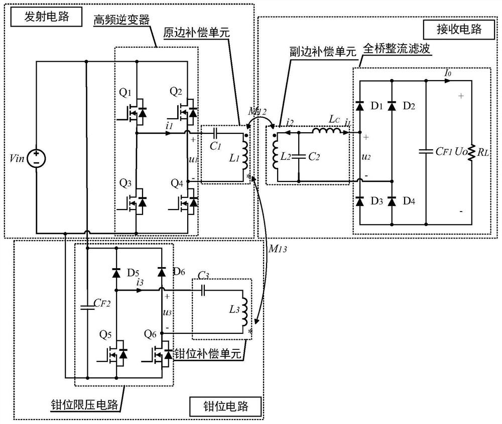
[0033] see figure 1 , the present invention proposes a constant-voltage constant-current wireless power transmission device based on three coils, including a transmitting circuit, a receiving circuit and a clamping circuit.

[0034] Wherein, the transmitting circuit includes a high-frequency inverter and a primary side compensation unit, and the primary side compensation unit includes an inductor L 1 and capacitance C 1 , and satisfy the series resonance relationship at the fixed operating frequency ω of the system The high-frequency inverter has two bridge arms, and one bridge arm includes a series switch tube Q 1 and switch Q 3 , the other bridge arm includes a series switch Q 2 and switch Q 4 . The midpoint of a bridge arm of the high-frequency inverter and the capacitor C 1 Connected at one end, the capacitor C 1 The other end of the inductor L 1 connected, the inductance...


PUM


Abstract

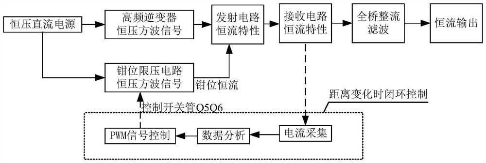
A constant-voltage constant-current wireless power transmission device based on three coils is obtained by improving a traditional wireless power transmission device and is composed of three parts. When the clamping circuit works, the constant-current characteristic of the transmitting circuit is realized through mutual inductance based on the set constant-voltage characteristic of the clamping circuit, so that the constant-current characteristic of the receiving circuit is realized; and when the clamping circuit is switched off, the constant voltage characteristic of the receiving circuit is realized through mutual inductance based on the constant voltage characteristic set by the transmitting circuit. A traditional constant-voltage type or constant-current type wireless power transmission device only considers wireless power transmission when the distance is fixed, and real constant-voltage or constant-current transmission with the variable distance cannot be achieved. Under the condition that the distance between the primary side coil and the secondary side coil is changed, the clamping circuit and the transmitting circuit are controlled, so that the constant-voltage and constant-current mode switchable output of the receiving loop can be realized, and distance-independent wireless electric energy transmission within a certain range can also be realized in a real sense.

Description

technical field [0001] The invention relates to the field of wireless power transmission, in particular to a constant voltage and constant current wireless power transmission device based on three coils. Background technique [0002] Wireless Power Transmission (WPT) refers to the conversion of electrical energy into other forms of energy (such as electromagnetic waves, mechanical waves, etc.) Ways of wireless power transmission over distance. There are a lot of complicated electrical wiring in the traditional wired power supply method, especially in the occasions where the construction is difficult such as walls, underwater and living organisms, and the charging of highly flexible equipment is required, the advantages of the wireless power transmission method are particularly prominent. In addition, wireless power transmission has significant advantages in reducing mechanical switch operations and improving power supply reliability, reducing physical consumables and constr...

Claims


Application Information

Patent Timeline
Patent Type & Authority Applications(China)
IPC IPC(8): H02J50/12H02M3/335H02M7/5387H02M7/06H02M1/088
CPCH02J50/12H02M3/3353H02M7/53871H02M7/06H02M1/088
Inventor 何良宗刘厚轩李乐程冰
Owner XIAMEN UNIV
Learn More