Two-level inverter common-mode voltage suppression method and system

A common-mode voltage and inverter technology, which is applied in the field of common-mode voltage suppression of two-level inverters, can solve the problems of not considering the common-mode current, reducing the reliability of the motor, increasing the manufacturing cost, etc., and achieving the reduction of sector selection , Suppression of common mode current, the effect of a wide range of applications

Pending Publication Date: 2022-05-06
JINGWEI HIRAIN (TIANJIN) RES&DEV CO LTD
View PDF0 Cites 1 Cited by
  • Summary
  • Abstract
  • Description
  • Claims
  • Application Information

AI Technical Summary

Problems solved by technology
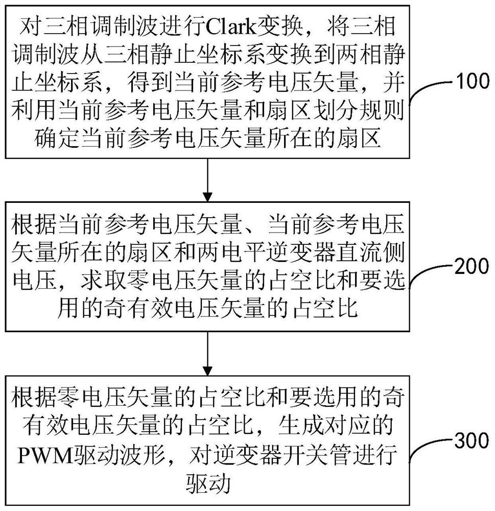
Adding a common-mode voltage filter at the output end of the two-level inverter can effectively suppress the common-mode voltage, but this setting destroys the compact structure of the two-level inverter, increases the manufacturing cost, and reduces the Reliability of Inverter Operation
The space vector modulation method that abandons the zero voltage vector uses a pair of redundant voltage vectors that are equal in size and opposite in direction to equivalently replace the zero voltage vector. Due to the introduction of redundant voltage vectors, the output performance of the two-level inverter is extremely high. big drop
At the same time, the space vector modulation method that abandons the zero-voltage vector does not consider the magnitude of the common-mode current generated by the common-mode voltage. The common-mode voltage generated by the two-level inverter will generate a common-mode current inside the motor, which will reduce the performance and performance of the motor. operational reliability

Method used


Image

  • Two-level inverter common-mode voltage suppression method and system
  • Two-level inverter common-mode voltage suppression method and system
  • Two-level inverter common-mode voltage suppression method and system

Examples


Embodiment Construction

[0073] The following will clearly and completely describe the technical solutions in the embodiments of the present specification in conjunction with the accompanying drawings in the embodiments of the present specification. Obviously, the described embodiments are only some embodiments of the present invention, not all embodiments. Based on the embodiments of the present invention, all other embodiments obtained by persons of ordinary skill in the art without making creative efforts belong to the protection scope of the present invention.

[0074] It should be noted that the terms "include" and "have" in the embodiments of this specification and the drawings, as well as any variations thereof, are intended to cover non-exclusive inclusion. For example, a process, method, system, product or device comprising a series of steps or units is not limited to the listed steps or units, but optionally also includes unlisted steps or units, or optionally further includes For other step...


PUM


Abstract

The embodiment of the invention provides a two-level inverter common-mode voltage suppression method and system, and the method comprises the steps: carrying out the Clark transformation of a three-phase modulation wave, converting the three-phase modulation wave from a three-phase static coordinate system to a two-phase static coordinate system, obtaining a current reference voltage vector, and carrying out the Clark transformation of the current reference voltage vector; determining a sector where the current reference voltage vector is located by using the current reference voltage vector and a sector division rule; according to the current reference voltage vector, the sector where the current reference voltage vector is located and the direct current side voltage of the two-level inverter, the duty ratio of a zero voltage vector and the duty ratio of an odd effective voltage vector to be selected are obtained; and according to the duty ratio of the zero voltage vector and the duty ratio of the odd effective voltage vector to be selected, generating a corresponding PWM driving waveform to drive an inverter switching tube. The common-mode voltage can be effectively suppressed, sector selection of the reference voltage vector is reduced, the calculation amount is reduced, and the method is easier to implement.

Description

technical field [0001] The invention relates to the technical field of motor control, in particular to a method and system for suppressing a common-mode voltage of a two-level inverter. Background technique [0002] The motor drive system is the main executive structure in the driving of new energy vehicles. Its driving characteristics determine the main performance indicators of the vehicle. It is an important part of the electric vehicle. Among them, the PWM motor drive system has been widely used in industrial systems and civil devices due to its good operating characteristics. However, the PWM frequency converter will generate high-frequency common-mode voltage during use, which will induce on the motor shaft. Shaft voltage will damage the bearing of the motor in a short time and shorten the service life of the motor, and the power electronic devices of high-speed switching will generate strong electromagnetic interference, which will interfere with the normal operation ...

Claims


Application Information

Patent Timeline
Patent Type & Authority Applications(China)
IPC IPC(8): H02M7/5387H02M7/483H02M1/12
CPCH02M7/53873H02M7/483H02M1/12
Inventor 王文圣
Owner JINGWEI HIRAIN (TIANJIN) RES&DEV CO LTD
Why Eureka
Try Eureka