Double-layer mixing pipe and residue-free mixing bin

A technology of mixing pipe and mixing materials, which is applied in the field of mixing silos, can solve the problems of inability to mix and discharge materials uniformly, uneven mixing of materials, and large vibration amplitude of the upper part, so as to achieve good product quality, uniform mixing of materials, and high efficiency. high effect

Pending Publication Date: 2022-05-10
NANJING XIANGRUI INTELLIGENT EQUIP TECH CO LTD +2
View PDF0 Cites 2 Cited by
  • Summary
  • Abstract
  • Description
  • Claims
  • Application Information

AI Technical Summary

Problems solved by technology

[0003] In the existing blending silo, a vibrator is usually installed on the top of the silo to provide power for the blending pipe to shake up and down, and the material in the bin is loosened by shaking the blending pipe up and down, so that the material can be quickly transferred from the feed The hole enters into the mixing tube, however, because the material in the lower part of the silo generates a greater pressure and the material is denser, the lower part of the mixing tube is subjected to greater pressure from the material, and the vibration amplitude of the lower part of the mixing tube is small and the vibration amplitude of the upper part is large. In some cases, the flow rate of the upper and lower materials into the blending pipe is different, resulting in uneven mixing of the materials and seriously affecting the product quality; in addition, there are usually multiple blending pipes evenly distributed in the existing blending silo, and the lower end of the blending pipe is conical The middle part of the bottom of the silo protrudes (refer to the utility model patent with application number 2018220585187), and the mixing pipe cannot cover the materials at the bottom of the conical silo, resulting in that different batches of materials at the bottom cannot be uniformly mixed and discharged

Method used


Image

  • Double-layer mixing pipe and residue-free mixing bin
  • Double-layer mixing pipe and residue-free mixing bin
  • Double-layer mixing pipe and residue-free mixing bin

Examples


Embodiment 1

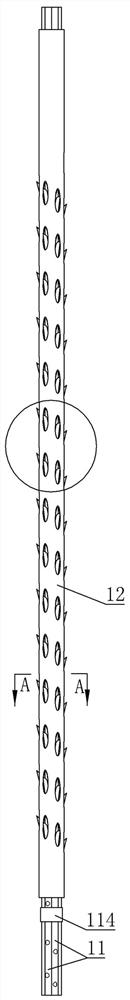
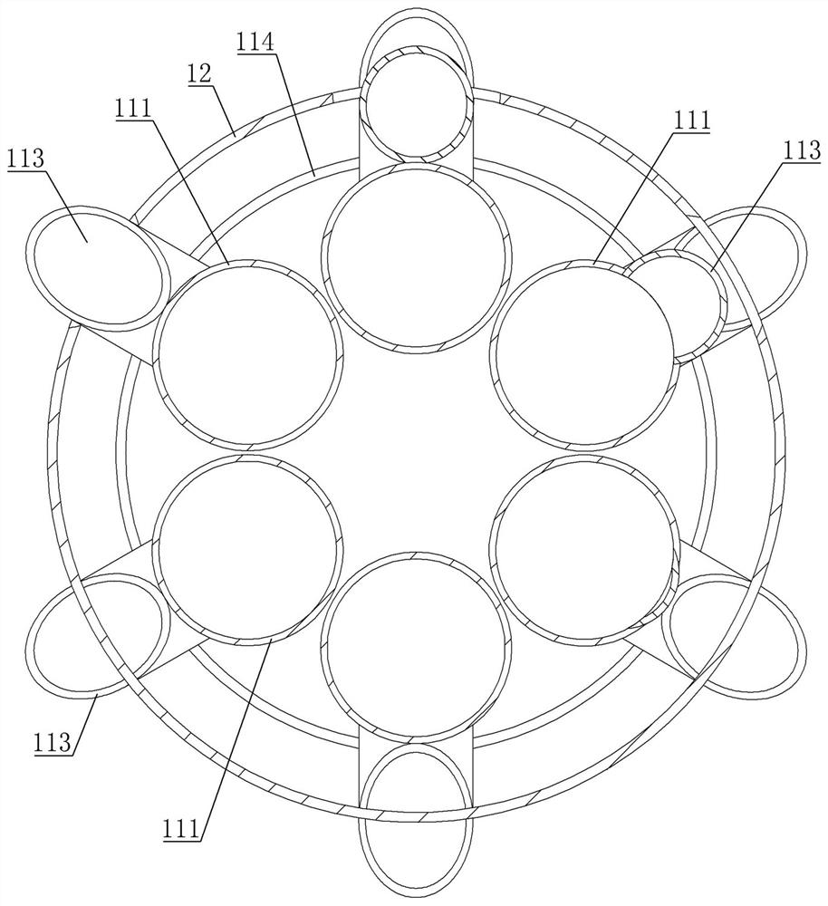
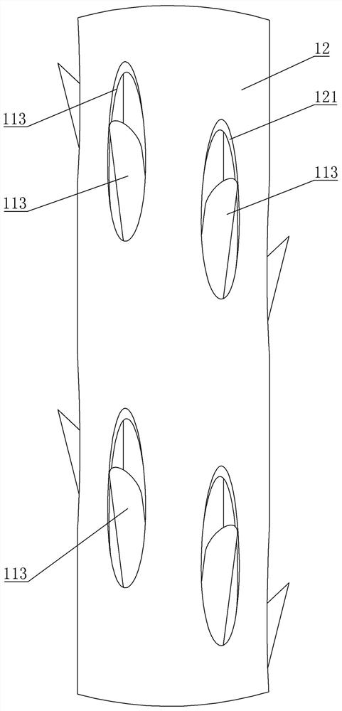
[0031] Embodiment 1, referring to the accompanying drawings 1-6 of the description, a double-layer blending material pipe, including an outer casing and a blending pipe, the outer side of the pipe wall of the blending pipe is provided with several feed holes at equal intervals along the direction of the busbar, correspondingly Adjacent feeding holes are staggered, and a group of feeding holes arranged in a spiral arrangement at equal intervals is formed on the wall of the mixing tube. This arrangement is more evenly distributed on the mixing tube, which is beneficial to the mixing of different batches of materials. The mixing pipe is discharged synchronously, and each feeding hole is fixedly connected with a feeding duckbill pipe inclined upward along the direction of the mixing pipe bus;

[0032] The outer casing is coaxially sleeved on the mixing pipe, and the size of the outer casing is larger than that of the mixing pipe. The pipe wall of the outer casing is provided with s...

Embodiment 2

[0034] Embodiment two, refer to the appended Figure 1-12, a non-residue blending silo, comprising a cylindrical silo with a conical silo bottom at the lower end, a collection silo coaxially fixed and set at the lower end of the conical silo bottom, the double-layer blending material described in claim 2 The lower part of the cylindrical silo is evenly distributed with a plurality of support seats.

[0035] The end cover of the cylindrical silo is evenly distributed with a plurality of vibration support components near the outer edge. The components include a cylindrical bracket vertically fixed on the surface of the end cover, a vibrator, a shock spring, and an end cover covered by the cylindrical bracket. A through hole is provided at the center, and the cushioning spring is set on the outside of the cylindrical bracket. The lower part of the outer surface of the cylindrical bracket is provided with an annular boss supported on the lower end of the cushioning spring. The up...


PUM


Abstract

According to the double-layer mixing pipe and the residue-free mixing bin, a mixing pipe in the bin is the double-layer mixing pipe, a mixing pipe bundle in the double-layer mixing pipe is fixedly connected with a vibration supporting plate arranged on an end cover, an outer sleeve is fixedly connected with a barrel-shaped support arranged on the end cover, an oval hole is formed in the outer sleeve, and the outer sleeve is fixedly connected with the barrel-shaped support. The feeding hole of the mixing pipe is provided with the inclined feeding duckbilled pipe extending out of the oval hole, the oval hole reserves a vibration space for the feeding duckbilled pipe, interference of the inner pipe and the outer pipe is avoided, and when the mixing pipe bundle vibrates to discharge materials, the outer sleeve bears the pressure of materials in the stock bin, so that the mixing effect is good. The problem of different vertical vibration amplitudes caused by different pressures of materials at the upper part and the lower part of the internal mixing tube bundle is solved, the flows of the materials at the upper part and the lower part entering the mixing tube are the same, and the materials are mixed more uniformly; in addition, each mixing tube bundle transmits vibration force to the auxiliary mixing tube in the conical bin bottom through the cross-shaped support, materials in different batches in the conical bin bottom can be mixed and discharged, and the whole mixing is more uniform.

Description

technical field [0001] The invention relates to the technical field of blending silos, in particular to a double-layer blending hopper and a non-residue blending silo. Background technique [0002] In the industrial field, in order to achieve relatively stable quality requirements for materials, it is necessary to blend different batches of materials. The gravity blending silo uses the full flow form of the materials in the silo to achieve uniform mixing by gravity flow. Materials of different heights in the blending silo enter the blending pipe through the feed holes of different heights on the blending pipe in the silo when the material is unloaded, and then send the materials into the blending chamber below through the conveying pipe, so that the different Batches of materials are simultaneously discharged from the blending chamber to obtain evenly mixed materials. [0003] In the existing blending silo, a vibrator is usually installed on the top of the silo to provide p...

Claims


Application Information

Patent Timeline
Patent Type & Authority Applications(China)
IPC IPC(8): B01F31/60B01F33/81B01F35/71
Inventor 姜姝周甲伟李冰邢学涛方树鹏刘士华王艳华
Owner NANJING XIANGRUI INTELLIGENT EQUIP TECH CO LTD
Why Eureka
Try Eureka