Automatic assembling device for express sorting telescopic machine

An assembly device and telescopic machine technology, applied in the direction of conveyor control devices, packaging, conveyors, etc., can solve the problems of lack of testing equipment, unable to effectively avoid express parcels, transportation damage, etc., to reduce express transportation damage and facilitate reassembly Effect

Pending Publication Date: 2022-05-10
芜湖市创赫钢结构有限公司
0 Cites 0 Cited by

AI-Extracted Technical Summary

Problems solved by technology

[0004] For this reason, the present invention provides an automatic assembly device for the express sorting telescopic machine, which effectively solves the lack of detection equipment b...

Method used

As shown in Figure 1, the present invention provides a kind of automatic assembly device for express delivery sorting telescopic machine, detection mechanism 3 is set at the blanking end of telescopic machine 1, and detection mechanism 3 detects packing or pasting When there is an abnormality in the article, the express parcel is transported back to the unpacking mechanism 5 through ...

Abstract

The invention discloses an automatic assembling device for an express sorting extendable conveyor, which comprises an extendable conveyor, an assembling machine, a detecting mechanism, a recycling mechanism and an unpacking mechanism, the assembling machine is used for packaging and strip pasting of expresses, and the detecting mechanism is used for detecting package damage and strip pasting completeness of warehoused express packages. And the recycling mechanism is used for conveying unqualified express packages back to the unpacking mechanism according to the detection result of the detection mechanism, and the unpacking mechanism is used for disassembling packages of the express packages recycled by the recycling mechanism. The detection mechanism is arranged at the discharging end of the telescopic machine, and the express packages are conveyed back to the unpacking mechanism through the recycling mechanism when the detection mechanism detects that the packages or the joint strips are abnormal, so that the situation that the express packages are damaged in the transportation process of the express sorting telescopic machine is avoided; and outer packages of the express packages are disassembled and recycled through the unpacking mechanism, reassembly of the express packages and recycling of damaged packages are facilitated, and the situation of express package damage is reduced.

Application Domain

Control devices for conveyorsSupporting frames +2

Technology Topic

Software engineeringAssembly machine

Image

  • Automatic assembling device for express sorting telescopic machine
  • Automatic assembling device for express sorting telescopic machine
  • Automatic assembling device for express sorting telescopic machine

Examples

  • Experimental program(1)

Example Embodiment

[0039] The following will clearly and completely describe the technical solutions in the embodiments of the present invention with reference to the accompanying drawings in the embodiments of the present invention. Obviously, the described embodiments are only some, not all, embodiments of the present invention. Based on the embodiments of the present invention, all other embodiments obtained by persons of ordinary skill in the art without making creative efforts belong to the protection scope of the present invention.
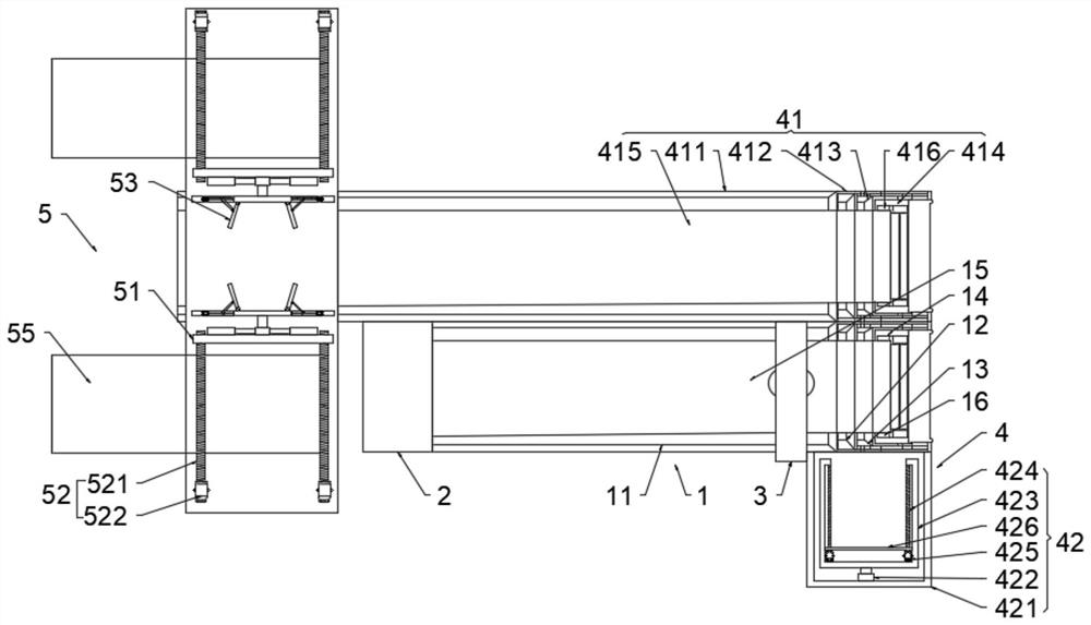
[0040] like figure 1 As shown, the present invention provides an automatic assembly device for express sorting telescopic machines. A detection mechanism 3 is provided at the feeding end of the telescopic machine 1, and when the detection mechanism 3 detects that the packaging or the stickers are abnormal, it is recovered by recycling Mechanism 4 transports the express package back to the unpacking mechanism 5, avoiding the damage of the express package during the transportation process of the express sorting telescopic machine, and disassembles and recycles the outer package of the express package through the unpacking mechanism 5, so as to facilitate the repacking of the express package. Recycling of assembly and damaged packaging reduces the situation of express delivery damage.
[0041] The present invention mainly comprises expansion machine 1, assembly machine 2, detection mechanism 3, recovery mechanism 4, and unpacking mechanism 5, and assembly machine 2 is arranged on the feeding end of expansion machine 1, and detection mechanism 3 is arranged on the discharge end of expansion machine 1 end, the recovery mechanism 4 is arranged side by side on the side of the telescopic machine 1, the unpacking mechanism 5 is arranged at the discharge end of the recovery mechanism 4, the assembly machine 2 is used to pack and paste the express delivery, and the detection mechanism 3 is used to check the storage The packaging damage of the express parcel and the integrity of the stickers, the recycling mechanism 4 is used to transport the unqualified express parcels back to the unpacking mechanism 5 according to the detection results of the testing mechanism 3, and the unpacking mechanism 5 is used to recycle through the recycling mechanism 4 The packaging of the courier package will be disassembled.
[0042] Wherein, assembly machine 2 can adopt the mode that manipulator carries out packing and sticking strip to express delivery, in addition, detection mechanism 3 is arranged on the upstream end of recovery mechanism 4, and detection mechanism 3 of the present invention can adopt the mode of camera collection image to come to express package. The integrity of the stickers is checked, and the outer packaging of the express package is checked for damage through infrared sensors.
[0043] Telescopic machine 1 among the present invention adopts prior art to realize, and telescopic machine 1 comprises fixed frame 11, the first mobile frame 12, the second mobile frame 13, the 3rd mobile frame 14, belt 15 and conveying roller 16, the first mobile The frame 12 is telescopically arranged on the fixed frame 11, the second mobile frame 13 is telescopically arranged on the first mobile frame 12, the third mobile frame 14 is telescopically arranged on the second mobile frame 13, and the transmission roller 16 is set to two, and the transmission roller 16 are respectively arranged on the two ends of the fixed frame 11 and the third mobile frame 14 that are far away from each other, and the belt 15 is arranged on the conveying roller 16, and the first mobile frame 12, the second mobile frame 13 and the third mobile frame 14 are adjusted by telescopic adjustment. To adjust the overall length of the telescopic machine 1, an additional driving source is provided in this embodiment, and the driving source drives the transmission roller 16 to rotate to drive the belt 15 for transportation.
[0044] The recovery mechanism 4 in the present invention is arranged on the end of the telescopic machine 1, that is, it is arranged on the third mobile frame 14. The recovery mechanism 4 is used to return unqualified express parcels. The recovery mechanism 4 of the present invention mainly adopts the following In a preferred embodiment, the recycling mechanism 4 includes a telescopic transmission frame 41 arranged side by side on the side of the telescopic machine 1, a return drive assembly 42 arranged at the end of the telescopic transmission frame 41, and an The transmission assembly 43 between the racks 41, the telescopic transmission frame 41 is used to transport the damaged express package to the unpacking mechanism 5, and the return drive assembly 42 is used to transfer the damaged express package from the telescopic machine 1 to the telescopic transmission On the frame 41 , the transmission assembly 43 is used as a transmission medium for the telescopic machine 1 to drive the telescopic transmission frame 41 to transmit in a direction opposite to the transmission direction of the telescopic machine 1 .
[0045] In this embodiment, the telescopic transmission frame 41 has the same structure as the telescopic machine 1 of the above-mentioned design, but the transmission direction is opposite. Therefore, the telescopic transmission frame 41 mainly adopts the following preferred embodiments. The telescopic transmission frame 41 includes a first return frame 411 , the second return frame 412, the third return frame 413, the fourth return frame 414, the return belt 415, and the transmission roller 416, the second return frame 412 is telescopically arranged on the first return frame 411, the second The three return racks 413 are telescopically arranged on the second return rack 412, and the fourth return rack 414 is telescopically arranged on the third return rack 413. There are two transmission rollers 416, and the transmission rollers 416 are respectively arranged on the first At the two ends of the material rack 411 and the fourth return rack 414 that are far away from each other, the return belt 415 is arranged on the transmission roller 416, and the transmission roller 416 is connected with the transmission roller 16 through the transmission assembly 43, and the transmission roller 16 rotates in the forward direction. Driven by the transmission of the component 43, the drive roller 416 is driven to rotate in reverse to drive the return belt 415 to be transported in reverse.
[0046] In the present invention, the telescopic transmission frame 41 has the same structure as the telescopic machine 1, but the size of each part is not the same. The second return frame 412, the third return frame 413, and the fourth return frame 414 correspond to the first A mobile frame 12, the second mobile frame 13, and the third mobile frame 14 have the same specifications, and the second return frame 412, the third return frame 413, and the fourth return frame 414 correspond to the first mobile frame 12, the fourth return frame 414, respectively. The second mobile frame 13 and the third mobile frame 14 do the same telescopic action, and the displacement of the telescopic action is the same. In order to facilitate the return drive assembly 42 to push the express package into the return belt 415, it is necessary to make the second return frame 412 , the third return rack 413 , and the fourth return rack 414 correspond to the same specifications as the first mobile rack 12 , the second mobile rack 13 , and the third mobile rack 14 respectively, and each corresponding action and action displacement are the same.
[0047] During the adjustment and movement of the second return rack 412, the third return rack 413, the fourth return rack 414, the first moving rack 12, the second moving rack 13, and the third moving rack 14, the first returning rack 411 Keeping the fixed frame 11 unchanged, in order to provide space for the unpacking mechanism 5, the length value of the first return frame 411 in this embodiment is greater than the length value of the fixed frame 11, and the assembly and feeding of the assembly machine 2 can be selected from the side While feeding.
[0048] The present invention makes the transmission roller 16 drive the transmission roller 416 to rotate through the transmission assembly 43, and the transmission assembly of the present invention mainly adopts the following preferred embodiments, as figure 2 As shown, the transmission assembly 43 includes a first transmission shaft 431 connected to the transmission roller 16, a first transmission gear 432 arranged on the first transmission shaft 431, a second transmission gear 433 engaged on the first transmission gear 432, The third transmission gear 434 engaged on the second transmission gear 433 and the second transmission shaft 435 connected to the transmission roller 416, the third transmission gear 434 is arranged on the second transmission shaft 435, the first return rack 411 and The fourth recycling frame 414 is provided with a mounting frame 436 for connecting the second transmission gear 433 .
[0049] The transmission process of the transmission assembly 43 is that the transmission roller 16 rotates to drive the first transmission shaft 431 to rotate, the first transmission shaft 431 drives the first transmission gear 432 to rotate, the second transmission gear 432 drives the third transmission gear 434 to rotate, and the third transmission gear 434 drives the second transmission shaft 435 to rotate, thereby driving the transmission roller 416 to rotate.
[0050] In this embodiment, the pitches of the first transmission gear 432, the second transmission gear 433, and the third transmission gear 434 are the same, the radii of the first transmission gear 432 and the second transmission gear 433 are the same, and the radius of the third transmission gear 434 is the same. Less than the radius of the first transmission gear 432 and the second transmission gear 433, because the radius of the first transmission gear 432 and the second transmission gear 433 is the same, so the rotation speeds of the first transmission gear 432 and the second transmission gear 433 are consistent, the third The radius of the transmission gear 434 is relatively small, that is to say, the third transmission gear 434 is driven to rotate more than one circle when the first transmission gear 432 and the second transmission gear 433 rotate one circle, so the rotation speed of the third transmission gear 434 Greater than the rotation speed of the first transmission gear 432 and the second transmission gear 433 .
[0051] The angular velocity of rotation of the first transmission shaft 431 is lower than the angular velocity of rotation of the second transmission shaft 435. In order to make the recovery transmission process faster than the transportation transmission process, that is to say, it is necessary to make the rotation linear velocity of the transmission roller 416 smaller than that of the transmission roller. 16 linear speed of rotation, in addition, in order to make the courier package can smoothly from the belt 15 to the return belt 415, it is necessary to make the apex of the transmission roller 16 and the apex of the drive roller 416 be on the same horizontal plane, therefore, when it is necessary to make the transmission roller When the rotational linear velocity of 416 is less than the rotational linear velocity of drive roller 16, (because linear velocity=angular velocity*radius) it is necessary to make the radius value of conveying roller 416 smaller than the radius value of drive roller 16.
[0052] When it is detected that the package is damaged or the sticker is damaged, the express package is pushed from the belt 15 to the return belt 415 by using the return drive assembly 42, and the return drive assembly 42 includes a drive cabin 421 arranged on the third moving frame 14 , the driving cylinder 422 arranged in the driving cabin 421, the U-shaped mounting bracket 423 connected to the driving cylinder 422, the threaded rod 424 arranged on both sides of the U-shaped mounting frame 423, and the first drive connected to the threaded rod 424 The motor 425 and the end of the threaded rod 424 are rotatably arranged on the U-shaped mounting frame 423 , the first driving motor 425 is fixedly arranged in the U-shaped mounting frame 423 , and the threaded rod 424 is threadedly connected with a push plate 426 .
[0053] The driving process of the return drive assembly 42 is to start the drive cylinder 422 after receiving the abnormal signal from the detection mechanism 3, and the drive cylinder 422 drives the U-shaped mounting frame 423 to stop and limit the express parcel. In order to make the U-shaped mounting frame 423 can completely stop the express parcel and avoid pushing the express parcel behind on the return belt 415, the side length data of the U-shaped mounting frame 423 is set to be consistent with the width data of the belt 15, and the driving cylinder 422 drives the U After the shaped mounting frame 423 is driven to stop the express parcel, the first drive motor 425 is driven to drive the threaded rod 424 to rotate, and the threaded rod 424 rotates to drive the push plate 426 to move forward to push the express parcel onto the return belt 415, and then pass Reverse driving the first driving motor 425 and the driving cylinder 422 drives the U-shaped mounting frame 423 and the push plate 426 to return to the initial position.
[0054] The express parcel is transported to the unpacking mechanism 5 via the return belt 415. The unpacking mechanism 5 is mainly used to remove the outer packaging of the express parcel so as to repack the outer package. The unpacking mechanism 5 of the present invention mainly adopts the following preferred embodiments, like image 3 As shown, the unpacking mechanism 5 includes an unpacking cabin 51 arranged at the feeding end of the telescopic transmission frame 41, a clamping drive assembly 52 and a clamping adjustment assembly 53 arranged in the unpacking cabin 51, The cutting machine 54 inside and the unloading conveyor belt 55 arranged in the unpacking cabin 51, the clamping and adjusting assembly 53 is used to clamp the express parcel with damaged packaging and adjust the position of the express parcel according to the shape of the express parcel. Make the cutting machine 54 cut the outer edge of the express parcel, and the clamping drive assembly 52 is used to drive the clamping and adjusting assembly 53 to move to the top of the telescopic transmission frame 41 to clamp the express parcel, and drive the express parcel after the cutting is completed. Drive the clamping and positioning assembly 53 to bring the outer packaging of the cut express parcel to the unloading conveyor belt 55 .
[0055] The clamping and positioning assembly 53 of the present invention mainly adopts the following preferred embodiments, as Figure 4 and Figure 5 As shown, the clamping and positioning assembly 53 includes a pair of translation seats 531 symmetrically arranged in the unpacking cabin 51, a positioning plate 532 arranged on the translation seat 531, and a positioning cylinder 533 arranged on the four sides of the positioning plate 532 , and the clamping main board 534 connected to the position adjustment plate 532, the position adjustment cylinder 533 is installed on the translation seat 531.
[0056]Drive the position adjustment cylinder 533 to drive the position adjustment plate 532 to move to drive the express parcel to move by clamping the main board 534, so that the cutting part of the cutting machine 54 just cuts the outer surface of the express parcel. In order to fully cut the outer surface of the express parcel, Rotating seat 5311 can be set on translation seat 531 (such as Figure 5 As shown), the translation base 531 is provided with a rotation source that drives the rotation base 5311 to rotate. The positioning cylinder 533 in this embodiment is arranged on the rotation base 5311, and the rotation of the rotation base 5311 can realize the comprehensive cutting of the express package.
[0057] In order to clamp both sides of the outer packaging after cutting, a clamping side plate 535 is rotated on the clamping main board 534, and an adjusting groove 536 is arranged in the clamping main board 534, and a second drive motor 537 is arranged in the adjusting groove 536. The second drive motor 537 is connected with a threaded rotating rod 538, and the threaded rotating rod 538 is threaded with a translation bolt 539, and the translation bolt 539 is rotatably connected with a support rod 5310. Side, in the initial state, the clamping side plate 535 is parallel to the clamping main board 534, and the second drive motor 537 is driven to drive the threaded rotating rod 538 to rotate, and the translation bolt 539 translates on the threaded rotating rod 538 under the rotation of the threaded rotating rod 538 , the translation pin 539 translates the push rod support rod 5310 to drive the clamping side plate 535 to rotate to clamp the two sides of the outer package of the express package.
[0058] The cutting machine 54 among the present invention cuts the outer package of the express package, and the cutting machine 54 includes a cutting shaft 541 arranged in the unpacking cabin 51, a cutting motor 542 connected to the cutting shaft 541, and a cutting motor 542 arranged on the cutting shaft. The cutting piece 543 on the bar 541, the cutting motor 542 drives the cutting piece 543 to rotate through the cutting shaft 541 to cut the outer packaging of the express parcel.
[0059] The clamping driving assembly 52 in the present invention is used to drive and drive the clamping and positioning assembly 53 to move to the top of the telescopic transmission frame 41 to clamp the express package, and after the cutting is completed, the driving and driving the clamping and positioning assembly 53 will be completed. The outer packaging belt of the cut express parcel is sent to the unloading conveyor belt 55, that is to say, the clamping drive assembly 52 mainly translates the clamping adjustment assembly 53 and unloads the express parcel external packaging, and the clamping drive assembly 52 includes Be arranged on the threaded drive rod 521 in the unpacking cabin 51 and the third drive motor 522 connected on the threaded drive rod 521, the two sides of the translation seat 531 are provided with threaded grooves for the threaded drive rod 521 to be threaded, the third drive The motor 522 drives the threaded drive rod 521 to rotate to translate the translation base 531 , the third drive motor 522 drives the threaded drive rod 521 to rotate, and the translation base 531 translates under the rotation of the threaded drive rod 521 .
[0060] In summary, the main implementation process of the present invention is to adjust the overall length of the telescopic machine 1 and the telescopic transmission mechanism 41, the express items are packaged and pasted at the assembly machine 2, and the telescopic machine 1 transmits the express parcel to the detection mechanism 3 for detection. When the detection mechanism 3 detects normal, the telescopic machine 1 transmits the express package to the feeding end, and when the detection mechanism 3 detects that it is abnormal, when the express package is transported to the return drive assembly 42, the cylinder 422 and the first drive motor are driven. 425 runs successively through the push plate 426 to push the express package to the return belt 415, the telescopic transmission frame 41 transmits the express package to the unpacking mechanism 5, and the third drive motor 522 drives the translation seat 531 to translate to the return belt 415. On the side, the second drive motor 537 and the positioning cylinder 533 drive the two sides of the express parcel to be clamped and the express parcel is translated, and the cutting motor 542 is started to drive the cutting piece 543 to rotate to cut the outer package of the express parcel. After one side is cut, the rotating seat 5311 rotates to drive the other side of the express package to cut the cutting piece 543. After the cutting is completed, the third drive motor 522 reversely rotates to drive the translation seat 531 to the feeding conveyor belt 55. When driving the second drive motor 537, the clamping side plate 535 is reset to the initial position and the clamping of the express package is released, so that the express package falls into the blanking conveyor belt 55 for blanking, and the express items fall during the cutting process. The top of the return belt 415 continues to unload to the recycling place, and the express items in the recycling place can be put back into the feeding end of the assembly machine 2 for reloading and packaging.
[0061] The above embodiments are only exemplary embodiments of the present application, and are not intended to limit the present application, and the protection scope of the present application is defined by the claims. Those skilled in the art may make various modifications or equivalent replacements to the present application within the spirit and protection scope of the present application, and such modifications or equivalent replacements shall also be deemed to fall within the protection scope of the present application.

PUM

no PUM

Description & Claims & Application Information

We can also present the details of the Description, Claims and Application information to help users get a comprehensive understanding of the technical details of the patent, such as background art, summary of invention, brief description of drawings, description of embodiments, and other original content. On the other hand, users can also determine the specific scope of protection of the technology through the list of claims; as well as understand the changes in the life cycle of the technology with the presentation of the patent timeline. Login to view more.
Why Eureka
Try Eureka