Wire frame for wire bundling machine and use method of wire frame

A technology for bundling machines and wire rods, which is applied in the direction of conveying filamentous materials, packaging/bundling items, transportation and packaging, etc. It can solve problems such as difficulty in ensuring accurate coiling of wire rods, dislocation extrusion, time-consuming and laborious, and improve packaging operations. The working method, avoiding misalignment and extrusion state, improving the effect of applicable performance

Active Publication Date: 2022-05-10
无锡瑞进智能工程有限公司
View PDF7 Cites 2 Cited by
  • Summary
  • Abstract
  • Description
  • Claims
  • Application Information

AI Technical Summary

Problems solved by technology

[0005] The purpose of the present invention is to: aim at the currently existing problem that many debris is easily attached to the outer wall after the wire rod is produced, and the device does not have the function of cleaning the outer wall of the wire rod, which leads to an oxidation reaction between the wire rod and air, which affects the quality of the wire rod; During the winding process, misalignment and extrusion are prone to occur, and it is difficult to ensure that the wire can be accurately wound on the winding roller; this device needs to manually transport the bundled wire to the baler for packaging, which is time-consuming Laborious, seriously affecting the working efficiency of the device

Method used

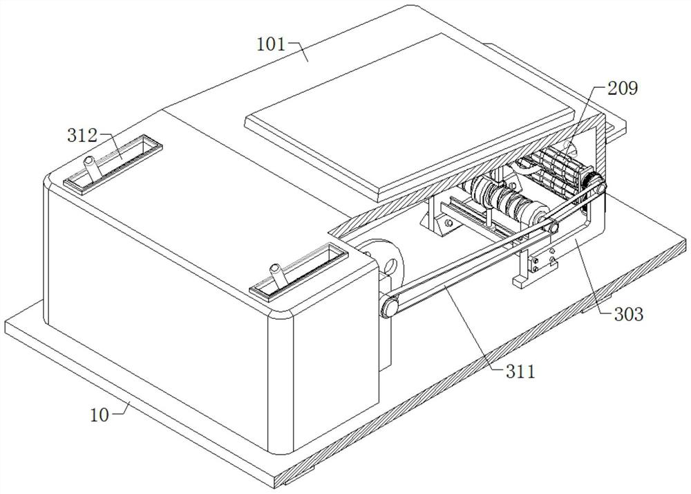
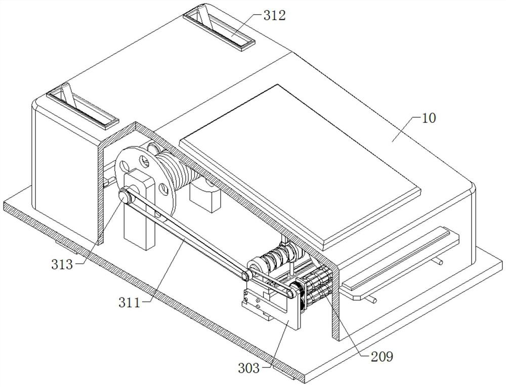
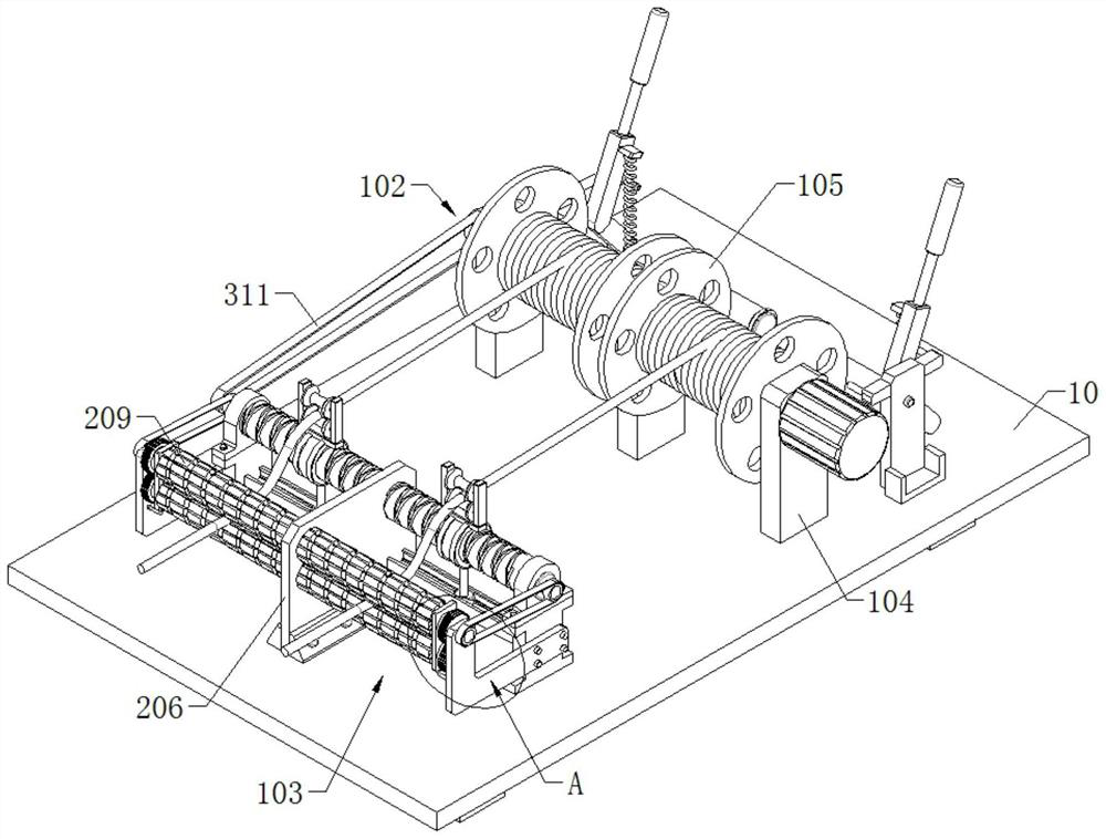

Image

  • Wire frame for wire bundling machine and use method of wire frame
  • Wire frame for wire bundling machine and use method of wire frame
  • Wire frame for wire bundling machine and use method of wire frame

Examples


Embodiment Construction

[0040] In order to make the purpose, technical solutions and advantages of the embodiments of the present invention clearer, the technical solutions in the embodiments of the present invention will be clearly and completely described below in conjunction with the accompanying drawings. Apparently, the described embodiments are some, not all, embodiments of the present invention.

[0041] Therefore, the following detailed description of the embodiments of the present invention is not intended to limit the scope of the claimed invention, but merely represents some embodiments of the present invention. Based on the embodiments of the present invention, all other embodiments obtained by persons of ordinary skill in the art without making creative efforts belong to the protection scope of the present invention.

[0042] It should be noted that, in the case of no conflict, the embodiments of the present invention and the features and technical solutions in the embodiments can be com...


PUM


Abstract

The invention provides a wire holder for a wire bundling machine and a using method thereof.The wire holder comprises a base and a box arranged at the top of the base, and further comprises a winding device fixedly connected to the top wall of the base and comprising a first winding mechanism and a second winding mechanism which are connected to the top of the base, each of the first winding mechanism and the second winding mechanism comprises a first connecting seat and an I-shaped plate which are connected to the top of the base station, the winding displacement device is fixedly connected to the top of the I-shaped plate, the winding displacement device is matched with the winding device through a first belt, an L-shaped plate and a second connecting seat are connected to the outer wall of the I-shaped plate, and the second connecting seat is fixedly connected to the top of the base station. The inner wall of the base table is connected with a film covering device. The end, away from the second connecting base, of the film covering device is matched with the winding device. The device is simple in structure and convenient to operate, oxidation reaction caused by contact between the wire and air can be avoided, it is guaranteed that the wire can be accurately wound around the winding roller, meanwhile, the working efficiency of the device is greatly improved, and automatic packaging and film covering of the wire are achieved.

Description

technical field [0001] The invention relates to the field of metal processing, in particular to a wire rack for a wire bundling machine and a method for using the same. Background technique [0002] In recent years, with the continuous development of high-speed wire rods, wire rods and wire rods have gradually become one of the most widely used steel types in my country's economic construction. The field has become an important new force in the production of wire rods. The wire rods are coiled in a hot state after being uncoiled and cooled. Since the integrated coils are relatively loose, the wire coils must be compressed to facilitate the transportation and storage of the coils. Bundling. At present, the coil bundling of high-speed wire production lines at home and abroad is all done by bundling machines. The equipment adopts hydraulic pressure, integrating machinery, electricity, hydraulics and instruments, with stable movements, high precision and high efficiency. Wire rod ...

Claims


Application Information

Patent Timeline
Patent Type & Authority Applications(China)
IPC IPC(8): B65H65/00B65H54/44B65H54/70B65H54/28B65B63/04B65B11/02
CPCB65H65/00B65H54/44B65H54/702B65H54/2818B65B63/04B65B11/025B65H2701/36B65H2801/81
Inventor 徐隽涛邓华叶斌朱晓依管文龙王盖
Owner 无锡瑞进智能工程有限公司
Why Eureka
Try Eureka