Medicine bottle packaging equipment
A technology for packaging equipment and medicine bottles, which is applied in packaging, packaging machines, transportation and packaging, etc., can solve the problems of laborious, low efficiency of bottle stoppers, high equipment costs, etc., and achieve the effect of saving working time and improving work efficiency
- Summary
- Abstract
- Description
- Claims
- Application Information
AI Technical Summary
Problems solved by technology
Method used
Image
Examples
Embodiment 1
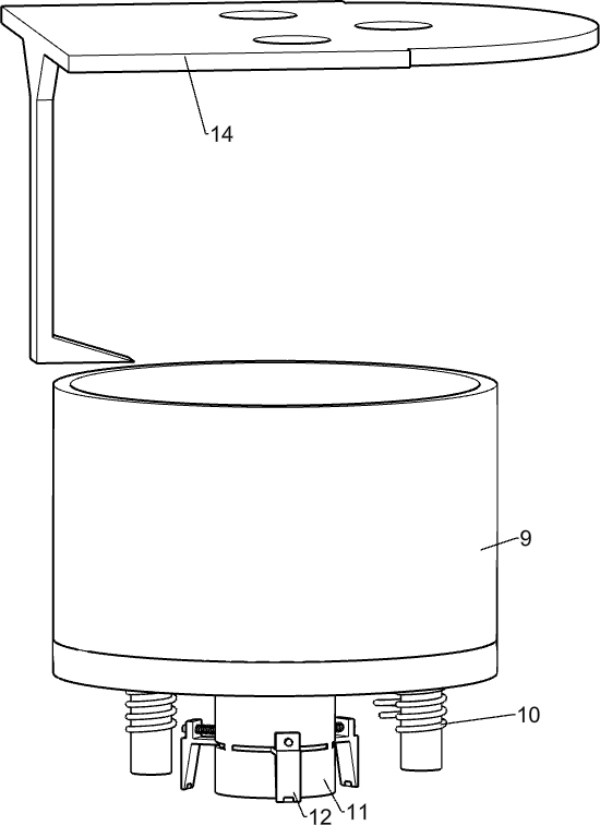
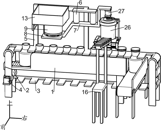
[0024] A medicine bottle packaging equipment, such as figure 1 As shown, it includes a feeding table 1, idler roller 2, feeding belt 3, feeding motor 4, drug feeding rod 5, cylinder 6, power rod 7, capping mechanism and material control mechanism, and the feeding table 1 is rotatably connected with Four supporting rollers 2, a slideway composed of supporting rollers is provided on the feeding platform 1, and a feeding belt 3 is wound on the four supporting rollers 2, and gaps for placing medicine bottles are arranged equidistantly on the feeding belt 3. On the right side of material table 1, there is a conveyor that conveys the capped medicine bottle out of the gap of feeding belt 3, which is shown in the figure but not marked, and feeding motor 4 is installed on feeding table 1, and the feeding motor The rotating shaft of 4 is fixedly connected with the external shaft of the idler roller 2 at the lower left, and the medicine feeding rod 5 is fixedly connected to the rear side...
Embodiment 2
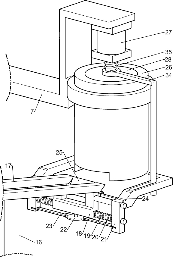
[0027] On the basis of Example 1, such as figure 1 , Figure 6 , Figure 8 and Figure 9As shown, the capping mechanism includes a top cover barrel 26, a top cover motor 27, a power plate 28, an electric push rod 29, a clamping plate 30, a clamping guide column 31, a clamping block 32, a clamping spring 33, a swing lever 34 and swing torsion spring 35, the power bar 7 right side is equipped with loam cake bucket 26, and the annular array in loam cake barrel 26 is provided with three vertical slack slideways, and the lower side of three slack slideways is communicated, power bar 7 The right side is equipped with loam cake motor 27, and the angle that loam cake motor 27 rotates every time is 60 degrees, and the rotating shaft of loam cake motor 27 is fixedly connected with power disc 28, and power disc 28 is slidably connected with loam cake bucket 26, and power disc 28 The bottom end is affixed with an electric push rod 29, and the lower end of the electric push rod 29 is af...
Embodiment 3
[0030] On the basis of Example 2, such as figure 1 , Figure 6 and Figure 7 As shown, the material control mechanism includes a feeding rack 16, a vibrating rod 17, an engaging block 18, an engaging rod 19, an engaging spring 20, a sliding rod 21, a rotating disc 22, a conducting rod 23, an upper connecting rod 24 and a material blocking block 25 , the front side of the feeding table 1 is equipped with a feeding rack 16, and two vibrating rods 17 for conveying rubber bottle stoppers are installed on the feeding rack 16, and the front side of the vibrating rod 17 is connected with a vibrating disc feeder, a vibrating disc The feeding machine is an existing technology, and the rubber bottle stopper can be continuously conveyed to the vibrating rod 17 through the vibrating disc feeding machine. Two connecting rods 19 are fixed symmetrically on the connecting block 18, and connecting springs 20 are sleeved on the connecting rods 19, and sliding rods 21 are slidably connected sy...
PUM
 Abstract
Description
Claims
Application Information
 - R&D
- Intellectual Property
- Life Sciences
- Materials
- Tech Scout
- Unparalleled Data Quality
- Higher Quality Content
- 60% Fewer Hallucinations
Browse by: Latest US Patents, China's latest patents, Technical Efficacy Thesaurus, Application Domain, Technology Topic, Popular Technical Reports.
© 2025 PatSnap. All rights reserved.Legal|Privacy policy|Modern Slavery Act Transparency Statement|Sitemap|About US| Contact US: help@patsnap.com


