Synthetic fiber rotary spinning system and spinning method

A technology of rotary spinning and synthetic fibers, applied in the field of spinning, can solve problems such as fast ejection speed, blockage of nozzles, inability to completely melt fiber polymer slices, etc., and achieve the effect of reducing the propulsion speed

Inactive Publication Date: 2022-05-10
桐乡市鑫晶源纺织有限公司
View PDF0 Cites 1 Cited by
  • Summary
  • Abstract
  • Description
  • Claims
  • Application Information

AI Technical Summary

Problems solved by technology

[0003] In the prior art, the extruding speed of the screw rotation directly affects the speed of the melt ejection, and the stall of the screw will cause the fiber polymer chips to be unable to melt completely, and the incompletely melted fiber polymer blocks the nozzle and cannot be spun , and the ejection speed is too fast, the spinning quality has problems
[0004] Therefore, the demand for high-reliability products is imminent, so we proposed a synthetic fiber rotary spinning system and spinning method, which has the functions of preventing the fiber polymer from being completely melted and blocking the spinning and controlling the spinning speed to prevent spinning. Quality suffers

Method used


Image

  • Synthetic fiber rotary spinning system and spinning method
  • Synthetic fiber rotary spinning system and spinning method
  • Synthetic fiber rotary spinning system and spinning method

Examples


Embodiment Construction

[0030] The following will clearly and completely describe the technical solutions in the embodiments of the present invention with reference to the accompanying drawings in the embodiments of the present invention. Obviously, the described embodiments are only some, not all, embodiments of the present invention. Based on the embodiments of the present invention, all other embodiments obtained by persons of ordinary skill in the art without making creative efforts belong to the protection scope of the present invention.

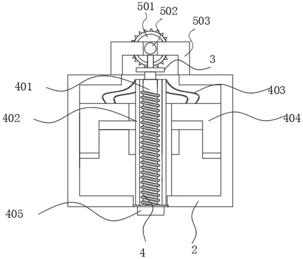
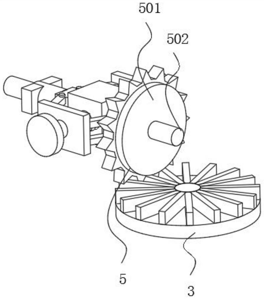
[0031] see Figure 1-6 , a synthetic fiber rotary spinning system, comprising a housing 1, the outer wall of the housing 1 is fixedly connected with a mounting frame 2, the inner wall of the mounting frame 2 is rotatably connected with a gear 3, and the bottom of the gear 3 is fixedly connected with a jetting assembly 4, and the jetting The assembly 4 includes a screw 401 , the outer wall of the screw 401 is rotatably connected with a spray pipe 402 .

[0032...


PUM


Abstract

The invention relates to the technical field of textile, and provides a synthetic fiber rotary spinning system which comprises a shell, a mounting frame is fixedly connected to the outer wall of the shell, a gear is rotatably connected to the inner wall of the mounting frame, a spraying assembly is fixedly connected to the bottom of the gear, and a maintaining assembly is connected to the outer wall of the gear in a meshed mode. The bottom of the maintaining assembly is movably connected with a speed reduction assembly. According to the synthetic fiber rotary spinning system and spinning method, the transmission teeth are in meshed connection with the gear, the rotation linear speed of the transmission teeth is the same as that of the gear, and the distance between the transmission teeth and the circle center of the gear is lengthened, so that the angular speed of the gear is slowed down; the rotating speed of the motor cannot be reduced immediately, so that the meshing position of the transmission teeth and the gear is changed, the rotating speed of the screw is reduced, and the spinning stability can be maintained due to the fact that the meshing position of the transmission teeth and the gear is variable and the angular speed is kept unchanged.

Description

technical field [0001] The invention relates to the technical field of spinning, in particular to a synthetic fiber rotary spinning system and spinning method. Background technique [0002] Spinning is to heat and melt the fiber-forming polymer slices in a screw extruder to form a melt, and then the melt is quantitatively, continuously and uniformly extruded from the pores of the spinneret. The spinning efficiency of the spinning equipment is high, and the spinning The silk quality is good, and the structure and performance of the fiber are perfected and improved. [0003] In the prior art, the extruding speed of the screw rotation directly affects the speed of the melt ejection, and the stall of the screw will cause the fiber polymer chips to be unable to melt completely, and the incompletely melted fiber polymer blocks the nozzle and cannot be spun , and the ejection speed is too fast, and the spinning quality has problems. [0004] Therefore, the demand for high-reliabi...

Claims


Application Information

Patent Timeline
Patent Type & Authority Applications(China)
IPC IPC(8): D01D5/18D01D5/08
CPCD01D5/18D01D5/08
Inventor 王哲明
Owner 桐乡市鑫晶源纺织有限公司
Why Eureka
Try Eureka