
Self-advancing and retreating type jet flow drill bit and drilling method

An advance and retreat, drill bit technology, which is used in drilling with liquid/gas jets, production of fluids, earth-moving drilling, etc. Effect

Pending Publication Date: 2022-05-10
CHONGQING UNIV
View PDF2 Cites 0 Cited by
  • Summary
  • Abstract
  • Description
  • Claims
  • Application Information

AI Technical Summary

Problems solved by technology

[0005] The purpose of the present invention is to provide a self-advance and retreat type jet drill bit and drilling method, which can solve the problems of high difficulty and low efficiency in retreating after the completion of jet drilling operation

Method used


Image

  • Self-advancing and retreating type jet flow drill bit and drilling method
  • Self-advancing and retreating type jet flow drill bit and drilling method
  • Self-advancing and retreating type jet flow drill bit and drilling method

Examples


Embodiment Construction

[0044] The present invention will be further described below in conjunction with accompanying drawing:

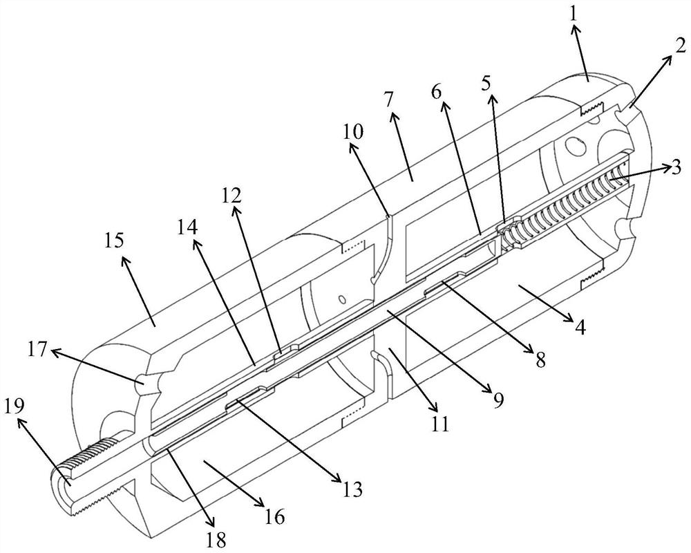
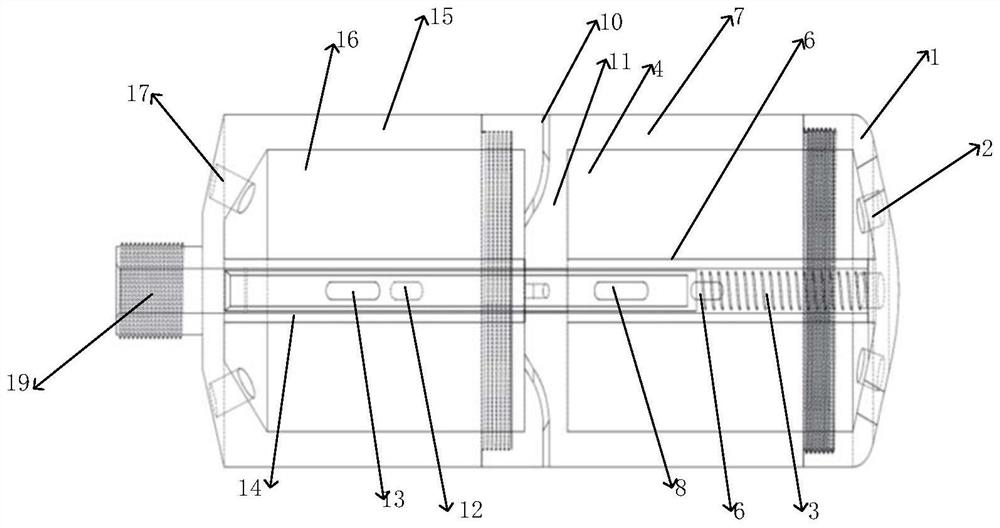
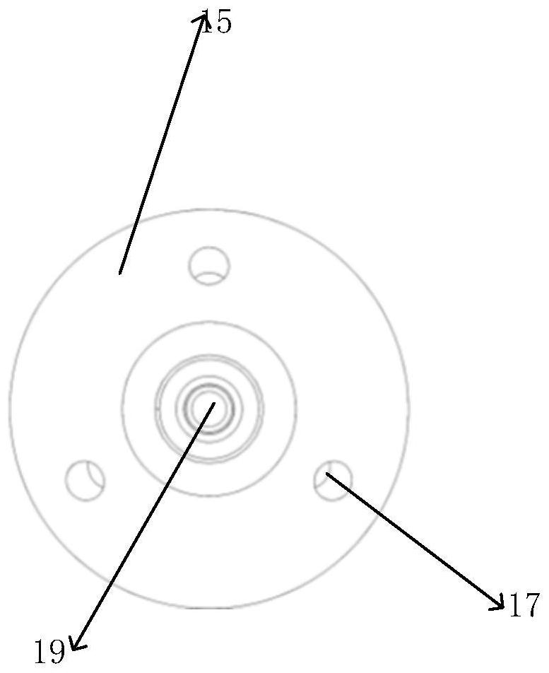
[0045] refer to Figure 1 to Figure 7 , a self-advancing and retreating jet drill bit is provided in this embodiment, which mainly includes a drill bit housing, and an independently arranged propulsion pressure-bearing chamber 16 and a coal-breaking pressure-bearing chamber 4 are formed inside the drill bit housing. A liquid inlet pipeline, the drill bit housing is provided with a drill bit liquid inlet 19 communicating with the liquid inlet pipeline, and the liquid inlet pipeline has a propulsion pressure chamber liquid inlet 12 communicating with the propulsion pressure chamber 14 and The coal-breaking pressure-bearing chamber liquid inlet 5 communicating with the coal-breaking pressure-bearing chamber 4; the propulsion nozzle 17 communicating with the propulsion pressure-bearing chamber 16 is also installed on the drill bit housing, and the coal-breaking bearing The coa...


PUM


Abstract

A drill bit end cover, a drill bit middle section and a drill bit rear section of the drill bit are sequentially in threaded connection, a coal breaking nozzle is in threaded connection with the drill bit end cover, a circumferential centralizing nozzle is in threaded connection with the drill bit middle section, and a propelling nozzle is in threaded connection with the drill bit rear section; the coal breaking pressure-bearing cavity and the propelling pressure-bearing cavity are separated through a pressure-bearing cavity baffle. The pressure adjusting spring is located in the coal breaking pressure-bearing cavity liquid inlet pipe. The coal breaking pressure-bearing cavity liquid inlet pipe is located at the axis of the coal breaking pressure-bearing cavity and welded to the drill bit middle section, and the propelling pressure-bearing cavity liquid inlet pipe is located at the axis of the propelling pressure-bearing cavity and welded to the drill bit rear section. The pressure regulating pipe is located in the propelling pressure-bearing cavity liquid inlet pipe and the coal breaking pressure-bearing cavity liquid inlet pipe, and the outer wall of the pressure regulating pipe and the inner walls of the propelling pressure-bearing cavity and the coal breaking pressure-bearing cavity liquid inlet pipe are sealed through gaps.

Description

technical field [0001] The invention belongs to the field of coalbed methane mining and drilling, in particular to a self-advancing and retreating jet drill bit and a drilling method. Background technique [0002] Coalbed methane is a clean energy, and its efficient development and utilization is of great significance to the adjustment of national energy structure. However, due to the special geological conditions in my country, about half of the coalbed methane wells are low-yield wells. Drilling multi-layer branch hole structure network fractures in the coal seam and connecting the fractures and the atmospheric environment through the wellbore can promote the rapid desorption and diffusion of the gas in the matrix under the condition of high pressure difference, thereby greatly increasing the single well production. [0003] Invention patent CN103924925A proposes "A Method and Device for Increasing Coal Seam Air Permeability by Hydraulic Jet Self-advancing Drilling". The ...

Claims


Application Information

Patent Timeline
Patent Type & Authority Applications(China)
IPC IPC(8): E21B7/18E21B43/00E21B43/26
CPCE21B7/18E21B43/006E21B43/2607
Inventor 刘文川汤积仁张慧栋冯淦陈长江王占昶崔向东
Owner CHONGQING UNIV
Learn More