Contact network isolation switch fault diagnosis device

A fault diagnosis device and isolating switch technology, applied to switches with movable electric contacts, electric switches, air switch components, etc., can solve problems such as catenary paralysis, movable contacts cannot be judged by difference, and simplify The difficulty of fault diagnosis and the effect of avoiding catenary paralysis

Pending Publication Date: 2022-05-10
EAST CHINA JIAOTONG UNIVERSITY
View PDF7 Cites 0 Cited by
  • Summary
  • Abstract
  • Description
  • Claims
  • Application Information

AI Technical Summary

Problems solved by technology

[0006] The above-mentioned patents all use waveforms to determine mechanical faults, but cannot judge whether the movable contact has reached the contact point based on the external drive mechanism and the difference in the angle of the driven shaft. At the same time, the above-mentioned patents cannot take timely compensation measures after diagnosing the mechanical fault, resulting in catenary failure. paralysis

Method used


Image

  • Contact network isolation switch fault diagnosis device
  • Contact network isolation switch fault diagnosis device
  • Contact network isolation switch fault diagnosis device

Examples


Embodiment 1

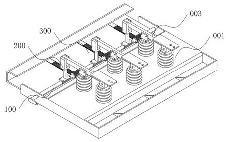
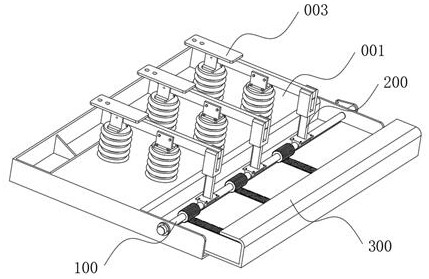
[0059] Such as Figure 1-2 As shown, a catenary isolating switch fault diagnosis device proposed by the present invention includes a driven shaft 100 that is rotatably installed on the contact switch frame 001. The fixed contact blade 003 is joined to form one or more movable contacts 200 in the closed state of the isolating switch. The movable contact 200 is in the shape of a fork, and when in contact with the fixed contact blade 003, the end of the fixed contact blade 003 is covered ( that is, figure 1 or the state shown in 2).

[0060] Such as Figure 5 As shown, the driven shaft 100 includes a shaft body 110 rotatably mounted on the contact switch frame body 001, and one end of the shaft body 110 is connected with an angle sensor 130 that acquires the offset angle when the shaft body 110 rotates;

[0061] The other end of the shaft body 110 is magnetically connected to the driving shaft 140. When the shaft body 110 and the driving shaft 140 are in the state of magnetic ...

Embodiment 2

[0083] Such as Figure 12-13 As shown, based on the first embodiment above, a catenary isolating switch fault diagnosis system proposed by the present invention includes the above-mentioned catenary isolating switch fault diagnosis device, and also includes a control center and is set in the control center for communicating to the contactor through the communication base station. A communication module for sending instructions to the network isolation switch fault diagnosis device;

[0084] The control center is used to control the rotation angle of the external drive mechanism; the catenary isolating switch fault diagnosis device receives the command from the control center through the information processing device and controls the compensation mechanism 300 and the electromagnetic chuck 113 to perform corresponding actions;

[0085] The information processing device sends the information acquired by the pressure sensor 290 and the angle sensor 130 to the control center throu...

Embodiment 3

[0090] Such as Figure 14 As shown, based on the above-mentioned embodiment 1 or embodiment 2, a method for diagnosing a fault of a catenary isolating switch proposed by the present invention, using the above-mentioned device for diagnosing a fault of a catenary isolating switch, includes the following steps:

[0091] S100: acquiring the driving stroke of the external driving mechanism;

[0092] If the external drive mechanism is a drive cylinder or an oil cylinder, the stroke represents the expansion and contraction of the drive cylinder or oil cylinder. If the external drive mechanism is a drive motor, the rotation angle of the drive motor is its drive stroke information. According to the drive stroke and the driven shaft 100 The supposed rotation angle of the driven shaft 100 is calculated.

[0093] S200: Obtain the rotation angle of the shaft through the angle sensor and compare it with the rotation angle of the output shaft of the drive mechanism in S100;

[0094] In th...


PUM


Abstract

The invention relates to the technical field of electrical equipment fault diagnosis, in particular to a contact network disconnecting switch fault diagnosis device. According to the technical scheme, the contact switch comprises a driven shaft which is rotatably installed on a contact switch frame body, the driven shaft is provided with one or more movable contacts which rotate along with the driven shaft and are jointed with a fixed contact blade of the disconnecting switch to form a closed state of the disconnecting switch, and the driven shaft comprises a shaft body which is rotatably installed on the contact switch frame body. The other end of the shaft body is magnetically connected with a driving shaft, and the other end of the driving shaft is fixedly provided with a connecting piece which is connected with an external driving mechanism and used for driving the driving shaft to rotate and further enabling the shaft body to rotate by a specific angle. According to the invention, the fault diagnosis difficulty of the external driving mechanism in the prior art is simplified, the reset operation which cannot be completed by the external driving mechanism after the fault is completed is remedied through the compensation mechanism, the contact network paralysis caused by the failure of closing is avoided, and the accuracy is high.

Description

technical field [0001] The invention relates to the technical field of fault diagnosis of electrical equipment, in particular to a fault diagnosis device for a catenary isolating switch. Background technique [0002] The isolating switch is a switching device that is mainly used to "isolate power supply, switch operation, connect and cut off small current circuits", and has no arc extinguishing function. When the isolating switch is in the off position, there is an insulation distance between the contacts that meets the specified requirements and an obvious disconnection mark; current switching device. It is generally used as a high-voltage disconnector, that is, a disconnector with a rated voltage above 1kV. Its working principle and structure are relatively simple, but due to the large amount of use and high requirements for working reliability, it is very important for the design, establishment and maintenance of substations and power plants. The impact on safe operatio...

Claims


Application Information

Patent Timeline
Patent Type & Authority Applications(China)
IPC IPC(8): H01H31/02H01H9/16H01H3/32H01H31/28
CPCH01H31/02H01H9/16H01H3/32H01H31/28
Inventor 石杰
Owner EAST CHINA JIAOTONG UNIVERSITY
Why Eureka
Try Eureka