
Wearable all-weather energy collection system

An energy harvesting, all-weather technology, applied in piezoelectric/electrostrictive or magnetostrictive motors, electrical components, AC network circuits, etc. A single problem, to achieve the effect of solving the limited capacity

Pending Publication Date: 2022-05-10
HARBIN INST OF TECH
View PDF0 Cites 0 Cited by
  • Summary
  • Abstract
  • Description
  • Claims
  • Application Information

AI Technical Summary

Problems solved by technology

However, the energy management circuits of existing micro-energy devices such as photovoltaic cells and vibration energy harvesters are designed for 1-2 micro-energy input channels, and it is difficult to efficiently manage the input energy of more than two micro-energy devices at the same time
However, for application scenarios such as human body wear, the parts with a large amount of mechanical vibration energy generally exist in the limbs, head and neck, etc., and the energy distribution is scattered, making it difficult to collect and manage
[0003] In addition, most of the existing technologies are designed for mature energy harvesting architecture systems such as "photovoltaic cells-lithium batteries". The types of micro-energy devices used are single and cannot achieve all-weather energy harvesting. High-efficiency power generation can only be achieved under good lighting conditions, but there is almost no power output under weak lighting conditions such as indoors and at night
[0004] Therefore, there is an urgent need for an energy system that simultaneously inputs and efficiently manages multiple micro-energy sources, which can be applied to various wearable and distributed power generation environments, and can make up for the problem of insufficient output capacity of photovoltaic cells in low-light environments.

Method used


Image

  • Wearable all-weather energy collection system
  • Wearable all-weather energy collection system
  • Wearable all-weather energy collection system

Examples


Embodiment Construction

[0026] Embodiments of the present invention are described in detail below, examples of which are shown in the drawings, wherein the same or similar reference numerals designate the same or similar elements or elements having the same or similar functions throughout. The embodiments described below by referring to the figures are exemplary and are intended to explain the present invention and should not be construed as limiting the present invention.

[0027] A wearable all-weather energy harvesting system proposed according to an embodiment of the present invention is described below with reference to the accompanying drawings.

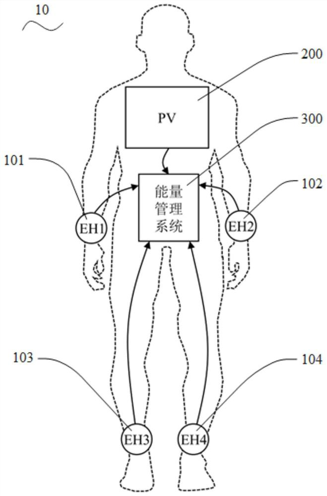
[0028] figure 1 It is a schematic structural diagram of a wearable all-weather energy harvesting system according to an embodiment of the present invention.

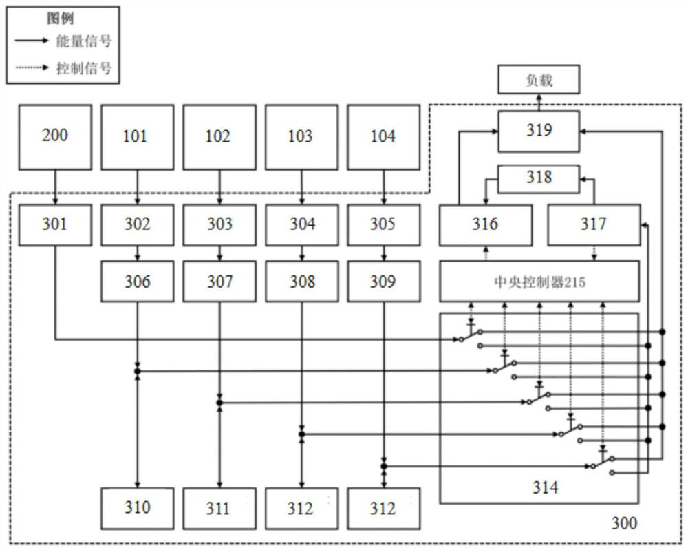
[0029] Such as figure 1 As shown, the wearable all-weather energy harvesting system 10 includes: a low-frequency vibration energy harvesting array 100 , a photovoltaic cell 200 and an energy m...


PUM


Abstract

The invention discloses a wearable all-weather energy collection system, and belongs to the field of energy collection, the wearable all-weather energy collection system comprises a low-frequency vibration energy collection array, a photovoltaic cell and an energy management module, the low-frequency vibration energy collection array comprises a first low-frequency vibration energy collection unit, a second low-frequency vibration energy collection unit, a third low-frequency vibration energy collection unit and a fourth low-frequency vibration energy collection unit, the output ends of the first, second, third and fourth low-frequency vibration energy collection units are connected with an energy input interface of the energy management module, are respectively arranged on four limbs of a human body, and convert low-frequency vibration energy generated by limb movement into alternating-current electric energy; an output end of the photovoltaic cell is connected with a direct-current input interface of the energy management module, is arranged at a position where the human body suffers from the maximum illumination, collects solar energy in the environment and converts the solar energy into direct-current electric energy; the energy management module efficiently distributes alternating-current electric energy and direct-current electric energy under complex energy input and storage conditions through a deep learning algorithm, electric energy can be provided for daily-carried small electronic equipment, and power grid energy does not need to be consumed.

Description

technical field [0001] The invention relates to the technical field of energy harvesting, in particular to a wearable all-weather energy harvesting system based on a low-frequency vibration energy harvester array and photovoltaic cells. Background technique [0002] With the increasingly tense energy issues, the use of renewable energy can effectively reduce the demand for fossil energy and reduce carbon emissions. In the daily activities of the human body, a large amount of mechanical energy is generated by body movement, and solar energy exists in the environment at the same time. By collecting these two energy sources at the same time, considerable electrical energy can be obtained whether it is indoors or outdoors. However, the energy management circuits of existing micro-energy devices such as photovoltaic cells and vibration energy harvesters are designed for 1-2 micro-energy input channels, and it is difficult to efficiently manage the input energy of more than two mi...

Claims


Application Information

Patent Timeline
IPC IPC(8): H02J3/38H02J3/46H02N2/18
CPCH02J3/38H02J3/466H02N2/186H02J2300/20H02J2300/24
Inventor 张宇峰李明雪
Owner HARBIN INST OF TECH
Learn More