Supercharge Your Innovation With Domain-Expert AI Agents!

Modular rotor structure of synchronous reluctance motor with high power factor

A technology of synchronous reluctance motor and high power factor, applied in the direction of magnetic circuit shape/style/structure, magnetic circuit rotating parts, magnetic circuit characterized by magnetic materials, etc., can solve the problem of reducing torque density and power factor Problems such as limited improvement and difficult processing can achieve the effect of saving material cost, reducing motor weight and improving mechanical strength

Pending Publication Date: 2022-05-10
HUNAN UNIV
View PDF2 Cites 0 Cited by
  • Summary
  • Abstract
  • Description
  • Claims
  • Application Information

AI Technical Summary

Problems solved by technology

[0003] At present, the mainstream of the motor market is still dominated by induction motors and permanent magnet synchronous motors. The main defect of synchronous reluctance motors is that the excitation components provided by the stator windings lead to low power factors, which restricts its application in high-performance occasions. The salient pole ratio of the rotor body can improve the power factor of the motor. Experts and scholars have carried out many designs and optimizations for the rotor body of the synchronous reluctance motor. The rotor body and the transversely laminated (TLA) rotor body, the ALA structure alternately laminates strong magnetically permeable materials and non-magnetically permeable materials (or air layers) in proportion and fixes them with bolts, and the cancellation of magnetic ribs and magnetic bridges in the middle of the magnetic barrier reduces The magnetic flux leakage and the maximum salient pole ratio of the rotor body are obtained, but its extremely complicated processing technology and low mechanical strength restrict the production and application of the motor with this structure. Therefore, the actual industrial application of the synchronous reluctance motor is based on the production cost The TLA rotor body structure is cheap, simple in processing, and high in mechanical strength. The TLA structure obtains a large salient pole ratio by punching out a multi-layer magnetic barrier structure on the rotor body laminations, but there are still deficiencies in motor performance:
[0004] ① Compared with the ALA structure, the salient pole of the TLA rotor body is relatively low, and its performance in terms of power factor and torque density is not as good as the former;
[0005] ② Part of the TLA rotor body topology reduces the quadrature axis inductance by setting up multi-layer magnetic barriers and increasing the proportion of magnetic barriers, thereby increasing the salient pole ratio. However, this method will also increase the saturation of the direct axis magnetic circuit at the same time. The improvement is limited;
[0006] ③ Part of the TLA rotor body topology removes the magnetic ribs and radial magnetic bridges of the rotor body, and increases the power factor of the motor by reducing magnetic flux leakage. However, this method has the problem of insufficient mechanical strength of the rotor body and increases the difficulty of motor processing. performance is still not ideal
[0007] Patent CN103701236A discloses a synchronous reluctance motor rotor structure with an outer rotor body. The innovation of the patent is that the magnetic pole units are designed on the yoke of the rotor body, and magnetic tracks are installed radially in each unit, and there are gaps between the magnetic tracks. The rotor body of this design has no The magnetic bridge structure can effectively improve the inductance difference between the alternating and direct axes and increase the power density of the motor rotor, but the size of each magnetic pole and each magnetic layer is different, and it needs to be fixed at the air gap, which is difficult to process. For the TLA structure rotor body Mechanical strength is also difficult to guarantee;
[0008] Patent CN102474139A discloses a modular rotor body for synchronous reluctance motors. Multiple rotor pole modules are used to segment along a common axis. Each rotor pole module includes multiple poles, and the magnetic layers of each pole are independent of each other. And fixed on the support plates on both sides of the rotor body of each section, this method realizes the modular design of the rotor poles, but the multi-layer support plates reduce the effective iron core length of the motor and thus reduce the torque density, and in the manufacturing process A large amount of non-magnetic materials are required for support and bonding, which cannot guarantee the mechanical strength of the motor, and problems such as magnetic pole asymmetry are prone to occur
[0009] None of the above methods and technologies can properly solve the problem of low power factor of synchronous reluctance motors without using permanent magnets and excitation windings of the rotor body. At present, there are related patents and documents in China that have not yet solved the problem of power factor of synchronous reluctance motors. Make an effective implementation case

Method used


Image

  • Modular rotor structure of synchronous reluctance motor with high power factor
  • Modular rotor structure of synchronous reluctance motor with high power factor
  • Modular rotor structure of synchronous reluctance motor with high power factor

Examples


Embodiment Construction

[0026] The following will clearly and completely describe the technical solutions in the embodiments of the present invention with reference to the accompanying drawings in the embodiments of the present invention. Obviously, the described embodiments are only some, not all, embodiments of the present invention. Based on the embodiments of the present invention, all other embodiments obtained by persons of ordinary skill in the art without making creative efforts belong to the protection scope of the present invention.

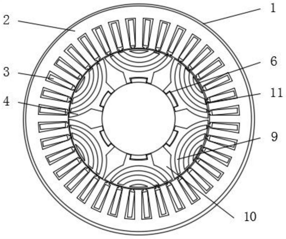
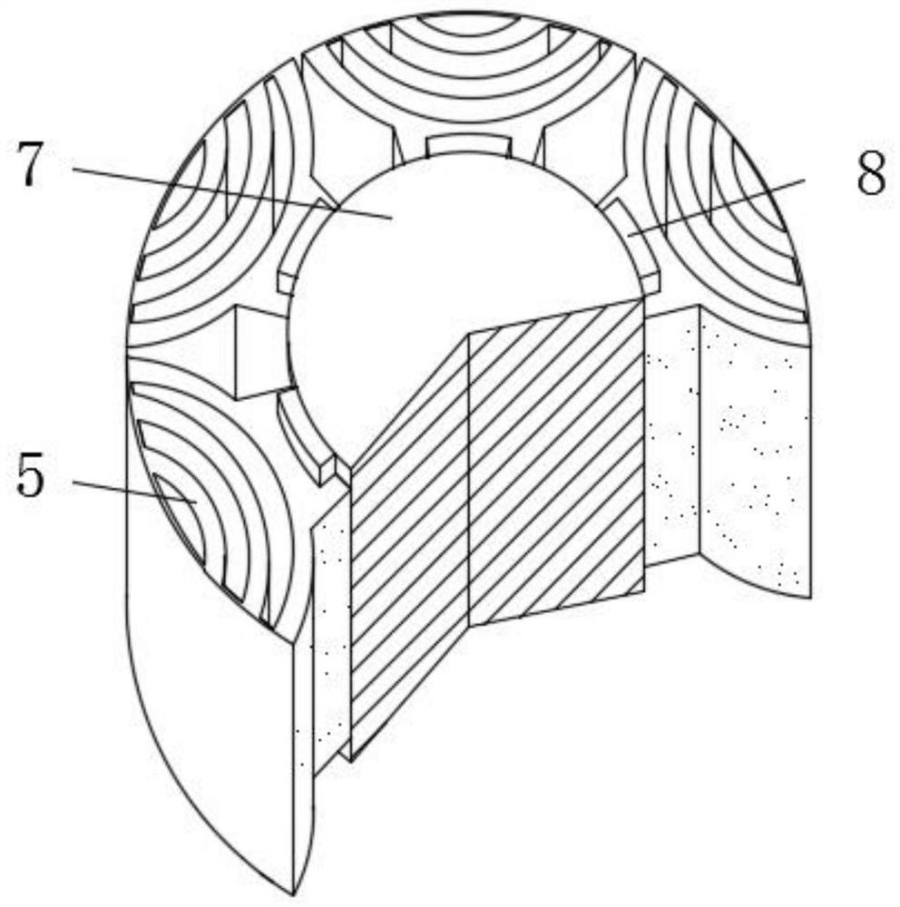
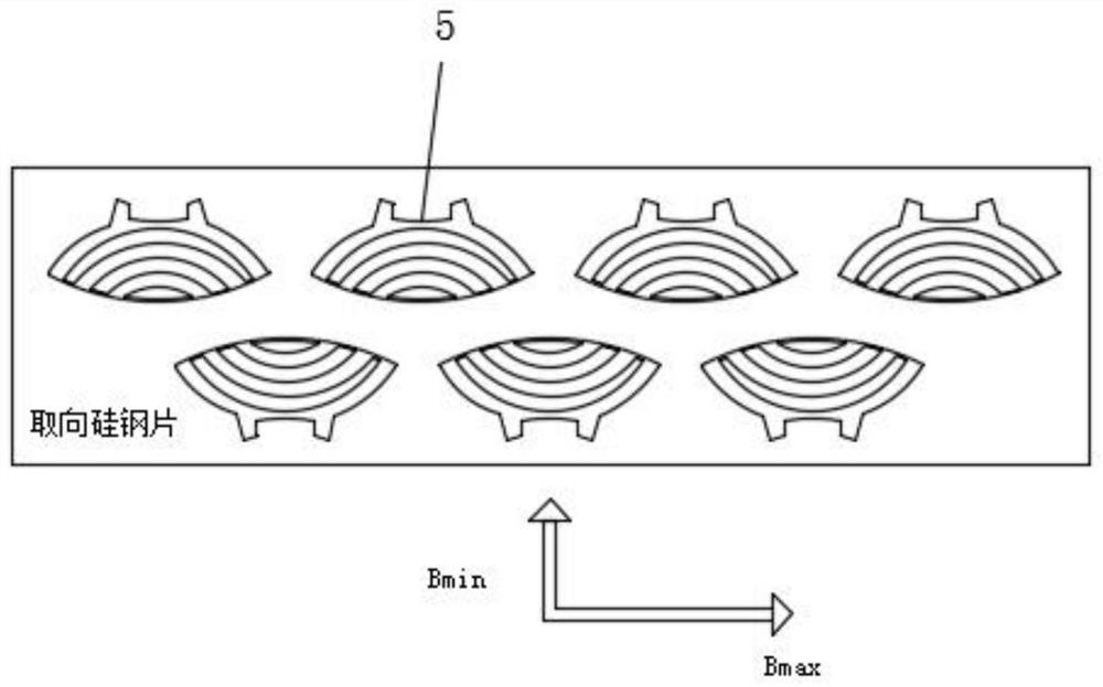
[0027] see Figure 1~3 , in an embodiment of the present invention, a high power factor synchronous reluctance motor modular rotor structure, including a motor casing 1, a stator core 2, a stator winding 3 and a rotor body 4, and a stator is installed inside the motor casing 1 Iron core 2, several stator windings 3 are wound in the stator iron core 2, a rotor body 4 is arranged inside the stator iron core 2, and the rotor body 4 includes six rotor pole modules...


PUM


Abstract

The invention discloses a modularized rotor structure of a synchronous reluctance motor with a high power factor, which comprises a motor shell, a stator core, a stator winding and a rotor body, and is different from a traditional synchronous reluctance motor topology in which a magnetic barrier is only arranged on a quadrature axis, and on the basis of a common synchronous reluctance motor rotor, direct-axis magnetic circuits between adjacent poles are separated, so that the direct-axis magnetic circuits between adjacent poles are separated; a layer of radial air magnetic barrier is added on a quadrature-axis magnetic circuit loop while the modular rotor with independent poles is formed, quadrature-axis magnetic resistance is increased, the salient pole ratio of the synchronous reluctance motor is increased, and the power factor of the motor is improved. And the extra material cost of motor production is not increased, the competitiveness of the synchronous reluctance motor in the fields of household appliances, industrial application and the like is improved, energy conservation and emission reduction are facilitated, and the process of replacing a traditional asynchronous motor by the synchronous reluctance motor is promoted.

Description

technical field [0001] The invention relates to the technical field of motors, in particular to a high power factor synchronous reluctance motor modular rotor structure. Background technique [0002] The synchronous reluctance motor follows the principle that the magnetic flux always closes along the path of the smallest reluctance, and the multi-layer magnetic barrier is set up through the rotor body to cause the difference in the reluctance of the orthogonal and direct axes, thereby generating magnetic pull to form torque, compared with ordinary permanent magnet synchronous motors , There is no rare earth permanent magnet material in the synchronous reluctance motor rotor, and it will not cause demagnetization due to environmental and operational problems such as high temperature or reverse magnetic field, which improves the reliability of the motor and avoids the high cost of rare earth permanent magnet materials. Compared with asynchronous motors, there is no squirrel ca...

Claims


Application Information

Patent Timeline
IPC IPC(8): H02K1/30H02K1/32H02K1/12H02K1/02H02K1/24
CPCH02K1/30H02K1/32H02K1/12H02K1/02H02K1/246
Inventor 冯垚径柯少宇夏晨曦黄守道
Owner HUNAN UNIV
Features
  • R&D
  • Intellectual Property
  • Life Sciences
  • Materials
  • Tech Scout
  • Unparalleled Data Quality
  • Higher Quality Content
  • 60% Fewer Hallucinations
Learn More