Centrifugal vacuumizing device

A vacuum device and centrifugal technology, applied in the direction of separation methods, liquid degassing, chemical instruments and methods, etc., can solve the problems of low cost, long degassing time, low degassing rate, etc., and achieve fast degassing, degassing The effect of high gas rate and increased contact area

Pending Publication Date: 2022-05-13
广东时利和汽车材料有限公司
View PDF0 Cites 0 Cited by
  • Summary
  • Abstract
  • Description
  • Claims
  • Application Information

AI Technical Summary

Problems solved by technology

The traditional stirring or static vacuum degassing technology is easy to use and low in cost. It is often used in the case of relatively low viscosity of the coating. For high-viscosity coatings, the stirring method is generally improved to increase the probability of the coating internally rolling to the surface. The contact area between the paint and the vacuum can remove the air mixed in the high-viscosity paint, but there are still problems such as long degassing time and low degassing rate

Method used


Image

  • Centrifugal vacuumizing device

Examples


Embodiment Construction

[0017] The following will clearly and completely describe the technical solutions in the embodiments of the present invention with reference to the accompanying drawings in the embodiments of the present invention. Obviously, the described embodiments are only some of the embodiments of the present invention, not all of them. Based on the embodiments of the present invention, all other embodiments obtained by persons of ordinary skill in the art without making creative efforts belong to the protection scope of the present invention.

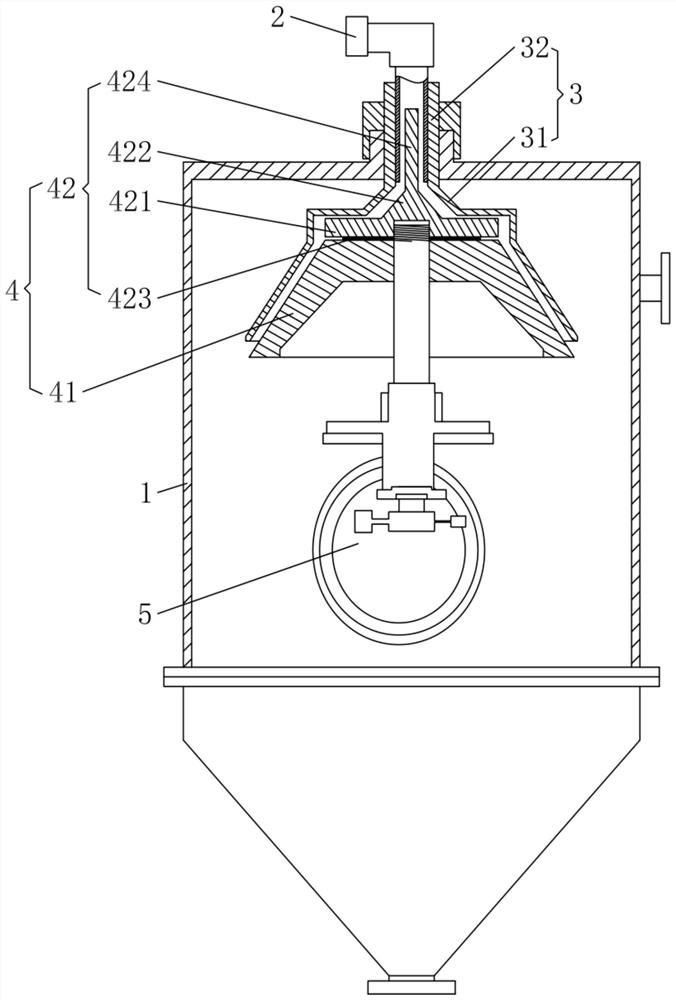
[0018] Please refer to figure 1 , a kind of centrifugal vacuum pumping device that the present invention provides, comprises vacuum jar 1, and feed port 2 is installed on described vacuum jar 1, and outer cover 3 is installed in described vacuum jar 1, and the bottom of described outer cover 3 The cover is provided with an inner shell structure 4 whose cross-section gradually increases from top to bottom. The outer cover 3 and the inner shell str...


PUM


Abstract

The invention discloses a centrifugal vacuumizing device which comprises a vacuum tank, wherein a feeding hole is formed in the vacuum tank; the vacuum coating machine is characterized in that an outer cover is installed in the vacuum tank, an inner shell structure with the section gradually becoming larger from top to bottom covers the lower portion of the outer cover, the outer cover and the inner shell structure are in clearance fit, and the upper end of the outer cover is communicated with the feeding port to form a channel enabling coating to flow into the vacuum tank sequentially through the feeding port, the outer cover and the outer wall of the inner shell structure. And the inner shell structure is connected with a driving motor so as to drive the inner shell structure to rotate and throw the coating flowing out of the channel onto the inner wall of the vacuum tank. The degassing device is suitable for high-viscosity coatings, and has the advantages of rapid degassing, high degassing rate and the like.

Description

technical field [0001] The invention relates to the field of vacuum pumping devices, in particular to a centrifugal vacuum pumping device. Background technique [0002] Polyurethane coatings for automobiles have a high viscosity, and are easy to wrap a large amount of gas during the process of preparation, production, transfer, etc., which will cause the performance of polyurethane coatings to decline after film formation, and accompanied by appearance defects, so the coatings need to be defoamed. The traditional stirring or static vacuum degassing technology is easy to use and low in cost. It is often used in the case of relatively low viscosity of the coating. For high-viscosity coatings, the stirring method is generally improved to increase the probability of the coating internally rolling to the surface. The contact area between the paint and the vacuum can remove the air mixed in the high-viscosity paint, but there are still problems such as long degassing time and low ...

Claims


Application Information

Patent Timeline
Patent Type & Authority Applications(China)
IPC IPC(8): B01D19/00
CPCB01D19/0026
Inventor 胡建华李艳许光耀王国元胡道生徐添宇
Owner 广东时利和汽车材料有限公司
Why Eureka
Try Eureka