A molding die for a refrigeration compressor body
A technology for refrigeration compressors and forming molds, applied in manufacturing tools, auxiliary welding equipment, welding equipment, etc., can solve the problems of low steel plate efficiency, affecting work efficiency, and great harm to workers.
- Summary
- Abstract
- Description
- Claims
- Application Information
AI Technical Summary
Problems solved by technology
Method used
Image
Examples
Embodiment 1
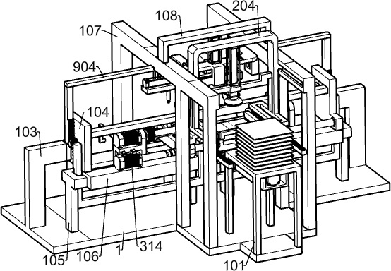
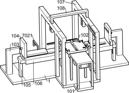
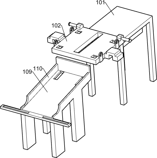
[0036] A refrigeration compressor body forming mold, such as Figure 1-15 As shown, it includes a base 1, a discharging table 101, a pushing table 102, a first bracket 103, a first support plate 104, a second bracket 105, a guide plate 106, a third bracket 107, a fourth bracket 108, and a processing seat 109. Processing baffle 110, feeding mechanism, coiling mechanism, welding mechanism, guiding mechanism, clamping mechanism and unloading mechanism, the front side of the base 1 is fixed with a discharging table 101, and the discharging table 101 is used to place the steel plate , two first brackets 103 are symmetrically installed on the base 1. The first brackets 103 are L-shaped and are located on the left and right sides of the base 1 respectively. The two first brackets 103 are symmetrically fixed with two first support plates. 104, two second brackets 105 are symmetrically fixed on the base 1, the second brackets 105 are T-shaped, and two guide plates 106 are symmetrically...
Embodiment 2
[0039] On the basis of Example 1, as image 3 and Figure 4 As shown, the feeding mechanism includes a first cylinder 2, an engaging frame 201, a pushing plate 202, a first toothed rod 203, a fifth bracket 204, a second air cylinder 205, an electric suction cup 206, a first toothed plate 207, a first The gear 208 and the second gear 209, the first cylinder 2 is installed on the discharge table 101, the telescopic shaft of the first cylinder 2 can be extended backward, and the telescopic shaft of the first cylinder 2 is installed with a connecting frame 201, and the connecting frame 201 A pusher plate 202 is fixed on the top, and the pusher plate 202 is slidably connected with the pusher table 102. The connecting frame 201 is symmetrically fixed with two first gear rods 203, and the first gear rods 203 are rectangular parallelepipeds with teeth at the top. Rod-shaped, a fifth bracket 204 is slidably connected to the two third brackets 107, the fifth bracket 204 is U-shaped, th...
Embodiment 3
[0042] On the basis of Example 2, as Figure 6-Figure 8As shown, the coiling mechanism includes a motor base 3, a first motor 301, a second support plate 302, a first shaft 303, a first sleeve 304, a third support plate 305, a second shaft 306, and a second sleeve 307 , the third gear 308, the third shaft 309, the fourth gear 310, the third sleeve 311, the fourth shaft 312, the fourth sleeve 313, the second motor 314 and the bidirectional screw 315, the two guide plates 106 are symmetrical on the There are two motor bases 3 in the sliding connection, the two motor bases 3 are symmetrical on the left and right, the first motor 301 is installed on the left motor base 3, the second support plate 302 is fixed on the left motor base 3, the second The support plate 302 plays a supporting role, a first rotating shaft 303 is connected to the rotating shaft of the first motor 301, the end of the first rotating shaft 303 away from the first motor 301 is rotatably connected with the seco...
PUM
 Abstract
Description
Claims
Application Information
 - R&D
- Intellectual Property
- Life Sciences
- Materials
- Tech Scout
- Unparalleled Data Quality
- Higher Quality Content
- 60% Fewer Hallucinations
Browse by: Latest US Patents, China's latest patents, Technical Efficacy Thesaurus, Application Domain, Technology Topic, Popular Technical Reports.
© 2025 PatSnap. All rights reserved.Legal|Privacy policy|Modern Slavery Act Transparency Statement|Sitemap|About US| Contact US: help@patsnap.com


