Hydraulic machine and method for continuous punching

A hydraulic press and hydraulic technology, applied in the field of hydraulic presses, can solve the problems of manual removal of molded parts, inability to directly discharge, and increase operating pressure, and achieve the effect of reducing intermittent consumption time, facilitating continuous hydraulic processing, and reducing operating pressure.

Inactive Publication Date: 2022-05-13
南通远飞锻压设备有限公司
View PDF0 Cites 2 Cited by
  • Summary
  • Abstract
  • Description
  • Claims
  • Application Information

AI Technical Summary

Problems solved by technology

[0002] Before the U-shaped workpiece with a horizontal hole is hydroformed by a hydraulic press, it is necessary to use special tools to cut the raw material to a fixed length and punch a fixed point. It is an intermittent operation. The intermittent operation takes some time and increases some operating pressure. At the same time, Molded parts need to be taken out manually and cannot be discharged directly

Method used


Image

  • Hydraulic machine and method for continuous punching
  • Hydraulic machine and method for continuous punching
  • Hydraulic machine and method for continuous punching

Examples


Embodiment 1

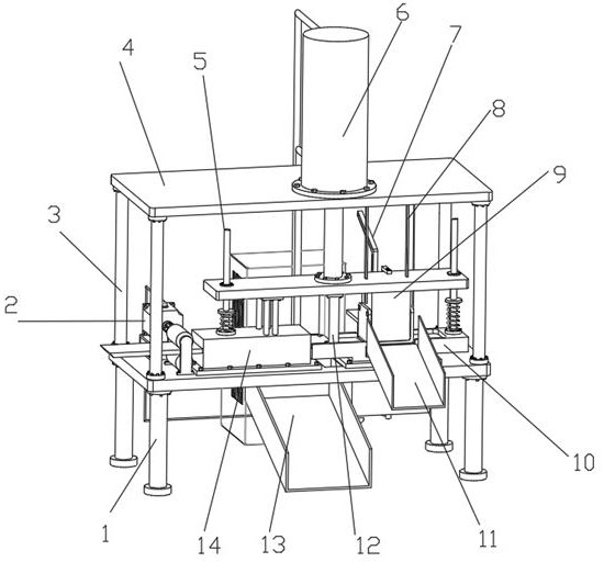
[0042] Such as Figure 1-7 As shown, the hydraulic press for continuous stamping includes a frame 1 and a control cabinet 24. A fixed-length hydraulic stamping assembly is arranged on the top of the frame 1. The fixed-length hydraulic stamping assembly is electrically connected to the control cabinet 24. The hydraulic stamping assembly performs fixed-length delivery of raw materials, Punch forming, end cutting and stamping;

[0043] The fixed-length hydraulic stamping assembly includes a height adjustment assembly, a fixed-length drive assembly, a punching assembly, an end cutting assembly, and a hydroforming assembly, and the punching assembly, the end cutting assembly, and the hydroforming assembly are connected to the height adjustment assembly;

[0044] The height adjustment assembly includes a support rod 3, a top plate 4, a hydraulic press 6 and a connecting plate 18. The support rod 3 is installed on the top of the frame 1, the top of the support bar 3 is fixed with a t...

Embodiment 2

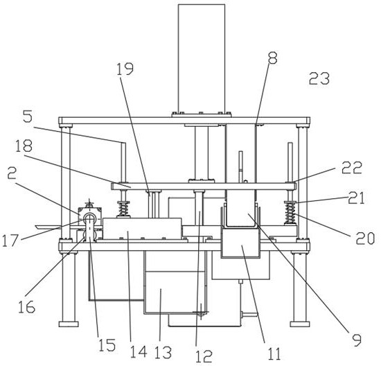
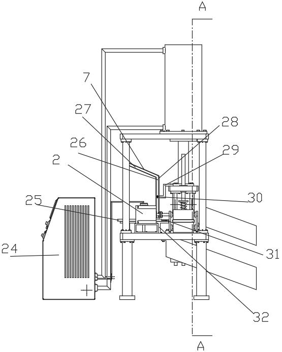
[0061] On the basis of embodiment 1, see Figure 3-7 As shown, the rear side wall of the fixed-length hydraulic stamping assembly is provided with a discharge assembly. The discharge assembly includes a reciprocating drive assembly, a pusher assembly, and a jacking assembly. The reciprocating drive assembly is connected to the pusher assembly. The components are connected, the pusher component and the jacking component are connected with the reciprocating drive component, the jacking component lifts the formed parts in the fixed-length hydraulic stamping component, the fixed-length hydraulic stamping component drives the reciprocating drive component to move back and forth, and the reciprocating drive component drives the pushing The material assembly moves back and forth to realize the ejection of molded parts.

[0062] The reciprocating drive assembly comprises a slant plate 7, a straight groove 26, a chute 27, a straight fixed plate 28, a connection block 29 and a push bear...


PUM


Abstract

The invention discloses a continuous stamping hydraulic machine and method, and relates to the technical field of hydraulic machines, the continuous stamping hydraulic machine comprises a rack and a control cabinet, the top of the rack is provided with a fixed-length hydraulic stamping assembly, the fixed-length hydraulic stamping assembly is electrically connected with the control cabinet, and the hydraulic stamping assembly sequentially carries out raw material fixed-length conveying, punching forming, end cutting and punching forming; a discharging assembly is arranged on the rear side wall of the fixed-length hydraulic stamping assembly and comprises a reciprocating driving assembly, a pushing assembly and a jacking assembly, and the reciprocating driving assembly is connected with the pushing assembly and the fixed-length hydraulic stamping assembly; by means of the mode, raw material fixed-length conveying, punching forming, end cutting and punch forming are sequentially and continuously operated, intermittent operation is not needed, intermittent consumed time is shortened, meanwhile, operation pressure is reduced, and continuous hydraulic treatment is facilitated.

Description

technical field [0001] The invention relates to the technical field of hydraulic presses, in particular to hydraulic presses and methods for continuous stamping. Background technique [0002] Before the U-shaped workpiece with a horizontal hole is hydroformed by a hydraulic press, it is necessary to use special tools to cut the raw material to a fixed length and punch a fixed point. It is an intermittent operation. The intermittent operation takes some time and increases some operating pressure. At the same time, Molded parts need to be taken out manually and cannot be discharged directly. [0003] Therefore, a hydraulic press and method for continuous punching are proposed to solve the above problems. Contents of the invention [0004] The object of the present invention is to provide a hydraulic press and method for continuous stamping to solve the problems raised in the above-mentioned background technology. [0005] In order to achieve the above object, the present i...

Claims


Application Information

Patent Timeline
Patent Type & Authority Applications(China)
IPC IPC(8): B21D35/00B21D28/24B21D28/02B21D43/04B21D45/02B21D55/00B21D22/02
CPCB21D35/00B21D28/24B21D28/02B21D43/04B21D22/02B21D45/02B21D55/00
Inventor 袁飞刘顺明王小青王娟夏明月
Owner 南通远飞锻压设备有限公司
Why Eureka
Try Eureka