Die-casting production equipment with part taking and spraying mechanism and part taking and spraying mechanism of die-casting production equipment

A spray mechanism and production equipment technology, applied in casting equipment, metal processing equipment, manufacturing tools, etc., can solve the problems of poor operating environment of the guide rail of the spray mechanism, shorten the service life of the guide rail and slider, and affect production efficiency, etc., to improve resource utilization. Utilization rate and work efficiency, avoiding large differences in product quality, good lubrication effect

Pending Publication Date: 2022-05-13
南京俊东机器人有限公司
View PDF0 Cites 0 Cited by
  • Summary
  • Abstract
  • Description
  • Claims
  • Application Information

AI Technical Summary

Problems solved by technology

[0003] Pick-up Spray The working arm of the linear robot separates the pick-up mechanism and the spray mechanism. When the spray mechanism is working, the guide rail of the spray mechanism operates in a harsh environment, high temperature and high humidity, and there are harmful impurities such as dust, metal debris, and water mist on the working surface, and the impurities will accelerate. The guide rail is corroded. When it enters the inside of the slider from the sealing surface of the linear guide rail, it is easy to cause the slider to be stuck and wear quickly, which greatly shortens the service life of the guide rail and the slider, thereby affecting production efficiency.

Method used


Image

  • Die-casting production equipment with part taking and spraying mechanism and part taking and spraying mechanism of die-casting production equipment
  • Die-casting production equipment with part taking and spraying mechanism and part taking and spraying mechanism of die-casting production equipment
  • Die-casting production equipment with part taking and spraying mechanism and part taking and spraying mechanism of die-casting production equipment

Examples


Embodiment Construction

[0029] The following will clearly and completely describe the technical solutions in the embodiments of the present invention with reference to the accompanying drawings in the embodiments of the present invention. Obviously, the described embodiments are only some, not all, embodiments of the present invention. Based on the embodiments of the present invention, all other embodiments obtained by persons of ordinary skill in the art without making creative efforts belong to the protection scope of the present invention.

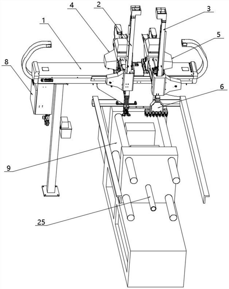
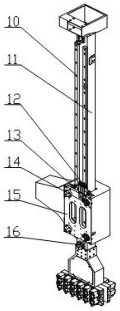
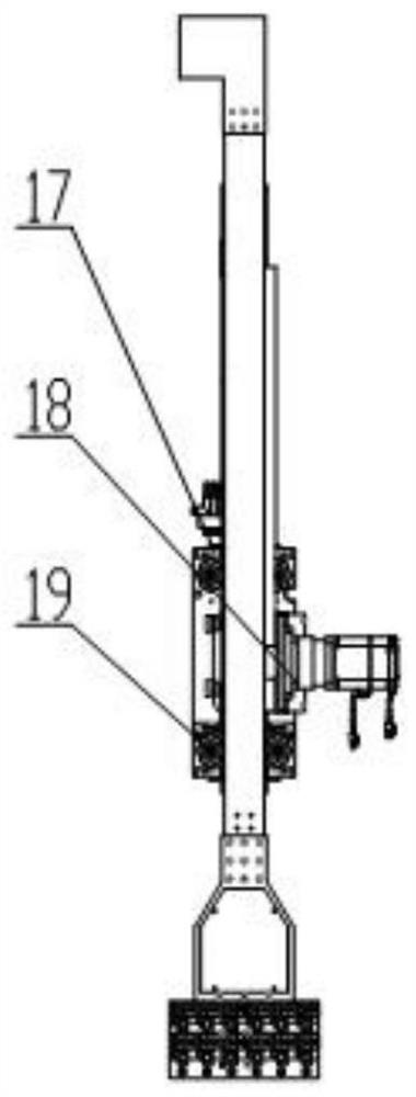
[0030] see Figure 5-Figure 9 , the present invention provides a technical solution: die-casting production equipment with a pick-up spray mechanism, including a die-casting machine 9 and a machine-side holding furnace 24, the machine-side holding furnace 24 is arranged on one side of the die-casting machine 9, and the die-casting machine 9 Including a sprue 25, the top of the sprue 25 is provided with a through soup injection port 26, the outer wall of the die-...


PUM


Abstract

A linear robot is arranged on the outer wall of a die-casting machine, the linear robot comprises an X shaft, the part taking mechanism, the spraying mechanism, a Y1 shaft, a Y2 shaft and a pneumatic control box, the X shaft is arranged on the outer wall of the die-casting machine, the Y1 shaft and the Y2 shaft are symmetrically arranged on the outer wall of the X shaft, the Y1 shaft and the Y2 shaft are both slidably connected with the X shaft, and the Y1 shaft and the Y2 shaft are slidably connected with the pneumatic control box. The taking mechanism is slidably arranged on the outer wall of the Y1 shaft, and the spraying mechanism is movably arranged on the outer wall of the Y2 shaft. According to the spraying mechanism, the structural design of guiding of the V-shaped rollers and the V-shaped rails is adopted, and the inherent defects that a linear guide rail is prone to rusting, untight in protection and low in reliability when used in a severe environment are overcome; the rolling body is wrapped by the V-shaped rolling wheel and is not influenced by water mist, dust and metal scraps in the operation environment; the motion precision of the linear robot is guaranteed, and the service life and the working stability of the rollers and the rails are improved.

Description

technical field [0001] The invention relates to the field of die-casting technology, in particular to die-casting production equipment with a pick-up spray mechanism and the pick-up spray mechanism. Background technique [0002] With the progress of science and technology and industrial production, especially with the development of industries such as automobiles, motorcycles and household appliances, die-casting technology has achieved extremely rapid progress and has been widely popularized and applied in various industries. The basic process of die-casting production is to inject molten metal into the sprue of the die-casting machine, and inject the molten metal into the mold of the die-casting machine through pressure to cool and form it. After the mold is opened, the picker removes the die-casting parts in the mold and passes The sprayer sprays the release agent on the mold for multiple cycles to obtain batches of solid metal castings. In the current die-casting indust...

Claims


Application Information

Patent Timeline
Patent Type & Authority Applications(China)
IPC IPC(8): B22D17/20B22D17/22B22D17/30B22D45/00
CPCB22D17/20B22D17/2272B22D17/2084B22D17/30B22D45/005
Inventor 赵静沈文军李名易
Owner 南京俊东机器人有限公司
Why Eureka
Try Eureka