Material conveying device capable of circularly feeding and discharging material layers

A technology for transporting materials and material layers, which is applied in the field of material conveying devices for circulating upper and lower material layers, which can solve problems such as high risk factor, high labor intensity, and employee injury, and achieve the effect of high degree of automation and improved production efficiency

Pending Publication Date: 2022-05-13
东莞市量必达智能科技有限公司
View PDF0 Cites 2 Cited by
  • Summary
  • Abstract
  • Description
  • Claims
  • Application Information

AI Technical Summary

Problems solved by technology

[0002] In the processing of the material industry, the material pallet is usually replaced manually. Because the material is heavy, it needs to be a professional laborer. The material falls off during heavy work and may cause injury to the employees.
[0003] As manufacturers in the smart card industry continue to increase their requirements for the working area and production capacity of the laminator, it is basically difficult to realize the traditional manual handling and pushing of materials, and the traditional operation process is inefficient, labor-intensive, and risky.
The existing laminator can realize automatic material transfer between the hot lamination tower and the cold lamination tower, but cannot realize automatic feeding and automatic discharging

Method used


Image

  • Material conveying device capable of circularly feeding and discharging material layers
  • Material conveying device capable of circularly feeding and discharging material layers
  • Material conveying device capable of circularly feeding and discharging material layers

Examples


Embodiment 1

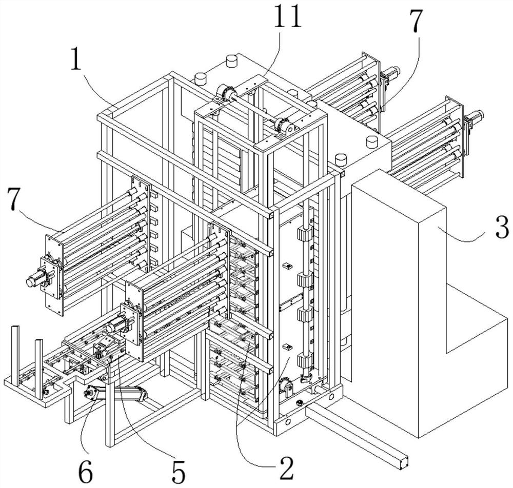
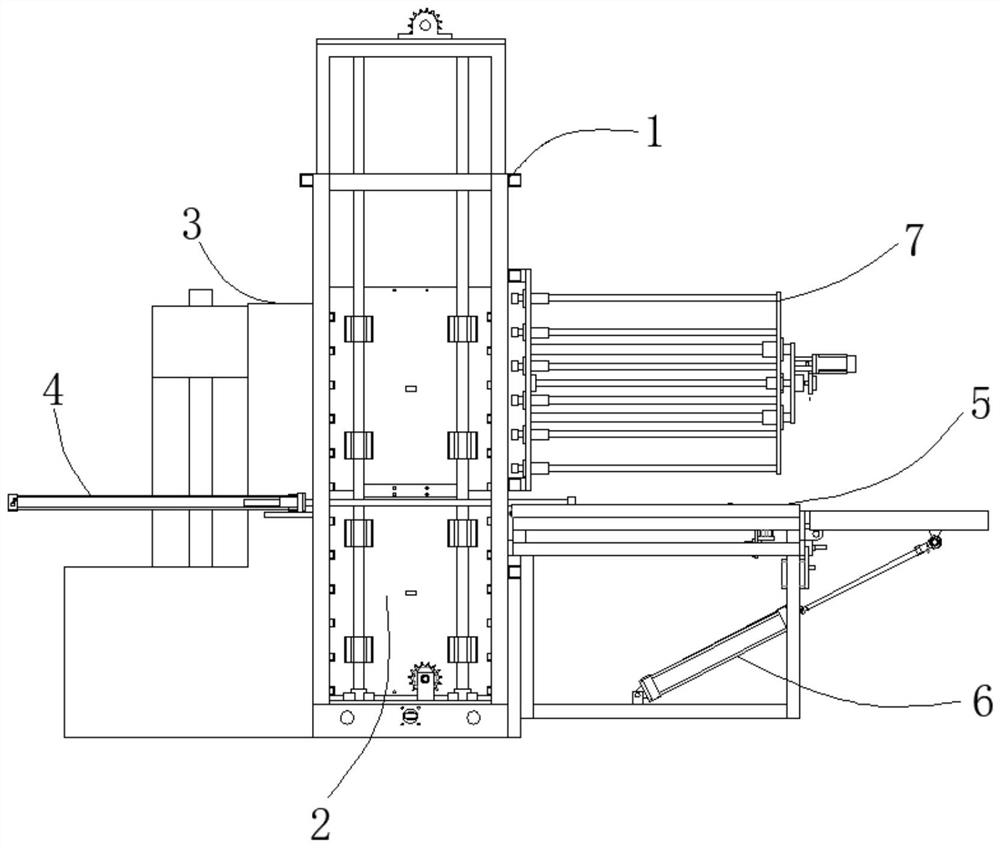
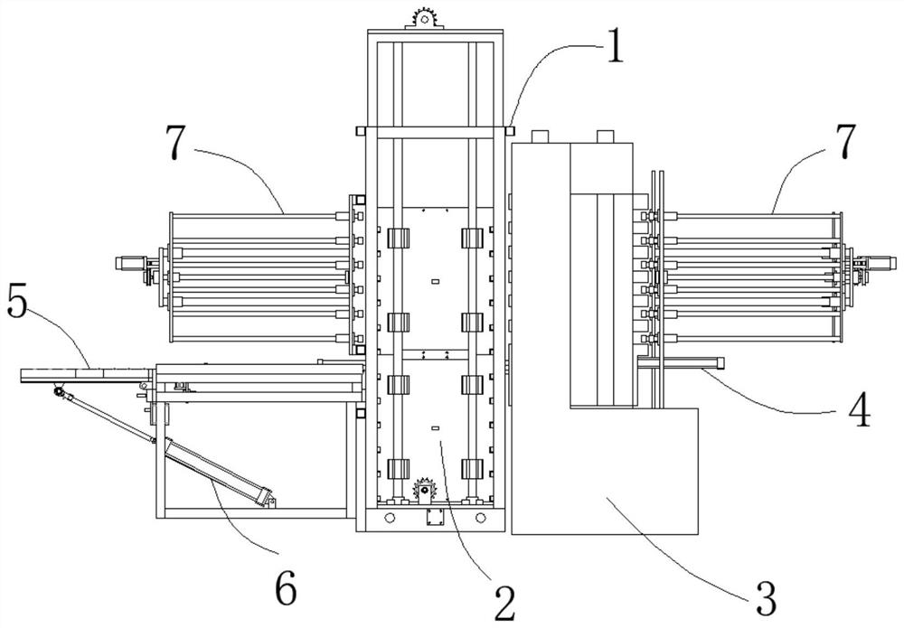
[0041] The invention proposes a conveying device for circulating upper and lower material layers. refer to Figure 1 to Figure 5 As shown, in Embodiment 1 of the present invention, the conveying device for circulating upper and lower layers includes a frame 1, a feeding platform 5 and a discharging platform 7, and one side of the frame 1 is connected to the feeding platform 7. The material table 5 is connected, and the other side of the frame 1 is connected with the discharge table 7, and a laminator 3 for processing material trays is arranged between the frame 1 and the discharge table 7; The pallet is first transported from the feeding table 5 through the frame 1 and enters the laminating machine 3. The laminating machine 3 is equipped with a hot press and a cold pressing machine, and the staff transports the pressed material pallet to the discharging table 7; The frame 1 is provided with a moving frame 11, one side of the moving frame 11 communicates with the feed table 5,...


PUM


Abstract

The invention discloses a material conveying device for circulating feeding and discharging layers, which comprises a rack, a feeding table and a discharging table, one side of the rack is connected with the feeding table, the other side of the rack is connected with the discharging table, and a laminating machine for processing a material tray is arranged between the rack and the discharging table; a material tray is firstly conveyed from the feeding table to enter the laminating machine through the rack; a movable frame is arranged in the rack, a guide rail for horizontal displacement of the movable frame is arranged at the lower end of the rack, a guide groove is formed in the lower end of the movable frame, the guide rail is in sliding connection with the guide groove, a material conveying box is arranged in the movable frame, the movable frame is provided with a lifting mechanism for vertically conveying the material conveying box, and the lifting mechanism conveys the material conveying box to be communicated with the feeding table and the laminating machine; the push-pull mechanism used for pushing and pulling the material trays is arranged on one side of the rack, the push-pull mechanism pushes in and out the material trays to be treated or treated, automatic feeding, discharging and transferring of the material trays are achieved, the automation degree is high, and the production efficiency is improved.

Description

technical field [0001] The invention relates to the technical field of automatic loading and unloading, in particular to a material conveying device for circulating upper and lower material layers. Background technique [0002] In the processing of the material industry, the material pallet is usually replaced manually. Because the material is heavy, professional laborers are required, and the material will fall off during the heavy work, which may cause injury to the employees. [0003] As manufacturers in the smart card industry continue to increase their requirements for the working area and production capacity of the laminator, it is basically difficult to realize the traditional manual handling and pushing of materials, and the traditional operation process is inefficient, labor-intensive, and risky. Existing lamination machines can realize automatic material transfer between the hot lamination tower and the cold lamination tower, but cannot realize automatic feeding an...

Claims


Application Information

Patent Timeline
Patent Type & Authority Applications(China)
IPC IPC(8): B65G47/82B65G47/74
CPCB65G47/82B65G47/74
Inventor 陈海亮马胜武
Owner 东莞市量必达智能科技有限公司
Why Eureka
Try Eureka