Supporting assembly for supporting central rotating shaft and central rotating shaft assembly

A technology for supporting components and central rotating shafts, which is applied in the directions of engine components, engine lubrication, turbine/propulsion device lubrication, etc., can solve the problems of large vibration amplitude of the central rotating shaft, and achieve the solution of excessive vibration amplitude and eliminate the stuck slot The effect of the risk of failure

Pending Publication Date: 2022-05-13
CHINA UNITED GAS TURBINE TECH CO LTD
View PDF0 Cites 0 Cited by
  • Summary
  • Abstract
  • Description
  • Claims
  • Application Information

AI Technical Summary

Problems solved by technology

[0006] The main purpose of the present invention is to provide a support assembly with adjustable stiffness of the

Method used


Image

  • Supporting assembly for supporting central rotating shaft and central rotating shaft assembly
  • Supporting assembly for supporting central rotating shaft and central rotating shaft assembly
  • Supporting assembly for supporting central rotating shaft and central rotating shaft assembly

Examples


Embodiment 1

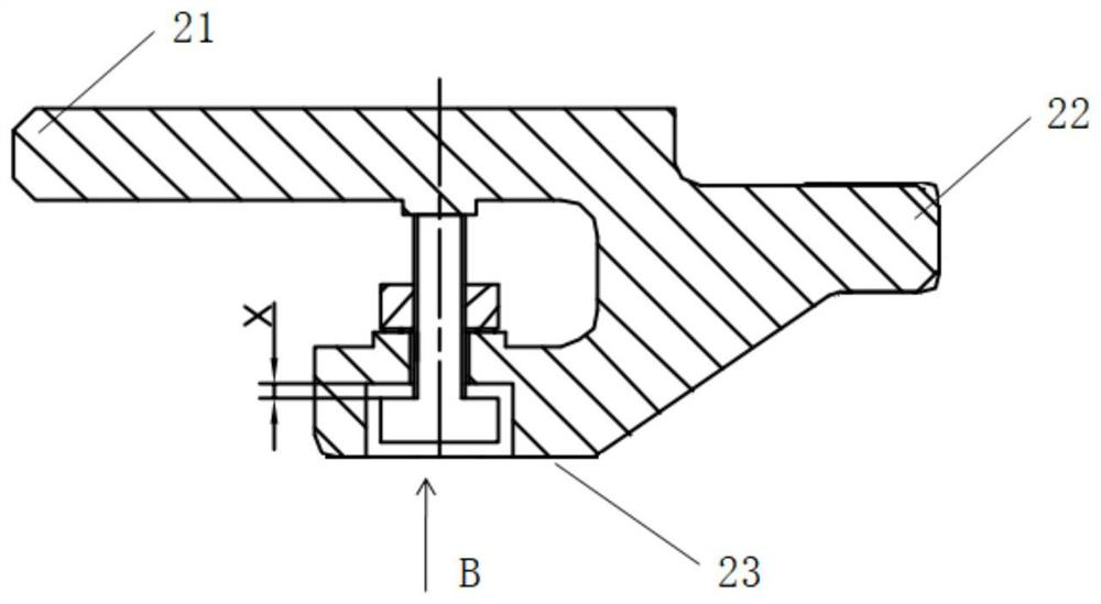
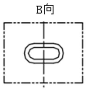
[0048] The rigidity adjusting member adopted in Embodiment 1 includes a first adjusting rod and a loosening preventing member. Such as figure 1 , Figure 4 As shown, the anti-loosening parts include fastening nuts 4 and anti-loosening washers 5, and the anti-loosening parts can also be set as double nuts, anti-loosening nuts and other structures that can achieve anti-loosening effects. The first adjusting rod in the first embodiment is the first anti-rotation adjusting rod 11, which includes a head and a rod, and the head is designed in an oval or rectangular shape.

[0049] Such as figure 1 As shown, the first support body 24 includes a first fixed end 21, a second fixed end 22 and a support end 23, the first fixed end 21 is matched with the first slot 9 of the front wheel disc 7, the second fixed end 22 is matched with the The second card slot 10 of the rear wheel disc 8 fits, and the supporting end 23 supports the central rotating shaft 1 . The first fixed end 21 and th...

Embodiment 2

[0056] Embodiment 2 On the basis of Embodiment 1, the adjustment method of the adjustment component is changed. The adjustment assembly is an elastic adjustment member, including a second adjustment rod, a compression pad 2, and a compression spring 6, and the second adjustment rod is arranged in the U-shaped opening through the compression pad 2 and the compression spring 6. The second adjusting rod in the second embodiment is the second anti-rotation adjusting rod 13, which includes a head and a rod. The head is oblong or rectangular in design to prevent the rod from loosening. The second anti-rotation adjusting rod passes through the support end 23 , and the compression spring 6 is pressed against the side surface of the first fixed end 21 through the anti-loosening piece and the pressing pad 2 .

[0057] Both ends of the pressing pad 2 are provided with annular grooves, one end is used to support the rod end surface of the second anti-rotation adjusting rod 13 , and the ot...

Embodiment 3

[0062] Embodiment 3 On the basis of Embodiment 2, the position of adjusting the gap X is changed. The adjustment assembly is an elastic adjustment member, including a second adjustment rod, a pressing pad 2 and a compression spring 6 . The second adjusting rod in the third embodiment is the second adjusting rod 14 with holes. The second adjusting rod 14 with a hole cooperates with the compression pad 2 and the compression spring 6 to adjust the rigidity of the support assembly. The head of the second adjusting rod 14 with a hole is arranged at a position away from the central rotating shaft 1 , the rod passes through the first fixed end 21 , and the compression spring 6 is pressed on the side surface of the supporting end 23 by the compression pad 2 . The pressing block 2 has two grooves, the upper groove is used to support the second adjusting rod, and the lower groove is used to define the top surface of the compression spring 6 . The compression spring 6 is arranged betwe...


PUM


Abstract

The invention discloses a supporting assembly used for supporting a central rotating shaft in a gas turbine, a front-stage wheel disc (7) and a rear-stage wheel disc (8) are assembled on the central rotating shaft (1) in the axial direction, the supporting assembly comprises a supporting body and an adjusting assembly used for adjusting the rigidity of the supporting body, and the supporting body is supported between the front-stage wheel disc (7) and the rear-stage wheel disc (8). The adjusting assembly is movably connected with the supporting body. When the frequency of the central rotating shaft (1) does not meet the requirement, the adjusting assembly can be adjusted to enable the supporting assembly to generate elastic deformation, so that the rigidity of the supporting assembly and the frequency of the central rotating shaft (1) are adjusted, and the vibration amplitude of the central rotating shaft (1) is reduced to meet the dynamic requirement of the gas turbine in the testing or operating process.

Description

technical field [0001] The invention relates to a heavy-duty gas turbine, in particular to a radial support assembly for the central rotating shaft of the heavy-duty gas turbine. Background technique [0002] The central shaft of the gas turbine is an important part of the rotor system, carrying the compressor disc and the turbine disc. The two ends of the central shaft are supported by the front shaft head and the rear shaft head. The central shaft has a large span. In the axial direction, radial support components need to be installed at different positions to support and adjust the frequency of the central shaft. [0003] In the prior art solution, the support assembly cooperates with the distance ring to radially support the central rotating shaft. The spacer ring and the front-stage wheel slot are usually fitted with interference. During the start-stop cycle of the gas turbine, due to the influence of transient deformation, the spacer ring and the front-stage wheel slo...

Claims


Application Information

Patent Timeline
IPC IPC(8): F02C7/20F02C7/06
CPCF02C7/20F02C7/06
Inventor 夏杰于洪飞孙晓杜永胜
Owner CHINA UNITED GAS TURBINE TECH CO LTD
Why Eureka
Try Eureka