Post-loading monitoring method for composite pile

A rear-mounted, combined pile technology, which is applied in the direction of measuring force, measuring devices, and infrastructure tests, can solve the problems of lack of reliable support for distributed optical fibers, inability to control temperature of distributed optical fibers, and damage and failure of distributed optical fibers. Achieve the effects of simple installation process, convenient measurement, and small impact on the measurement environment

Pending Publication Date: 2022-05-13
中铁二十二局集团市政工程有限公司 +1
View PDF0 Cites 0 Cited by
  • Summary
  • Abstract
  • Description
  • Claims
  • Application Information

AI Technical Summary

Problems solved by technology

[0003] The existing distributed optical fiber is usually pre-fixed on the steel bar, and the excess concrete on the surface is removed after the concrete is poured, which makes the distributed optical fiber very easy to damage and fail during construction, and the survival rate of the instrument is low
Now there are also post-installed distributed optical fibers, which require additional U-shaped installation pipes to be reserved in the cast-in-place pile, and the installation and construction are cumbersome; the temperature correction of the installed distributed optical fibers cannot be performed, and the measurement error is relatively large; grouting in the installation pipes It is easy to damage the distributed optical fiber, the stability is poor, and the distributed optical fiber lacks reliable support

Method used


Image

  • Post-loading monitoring method for composite pile
  • Post-loading monitoring method for composite pile
  • Post-loading monitoring method for composite pile

Examples


Embodiment 1

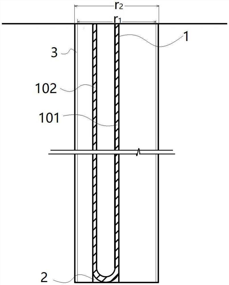
[0045] Such as figure 1 As shown, a post-installation monitoring method for composite piles, the specific steps are as follows:

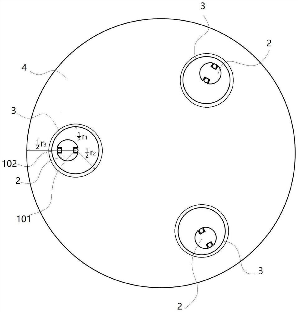
[0046] S1, fix, fix the distributed optical fiber 1 on the specified position of the PVC pipe 2, the PVC pipe 2 is respectively provided with a sealing groove 201 and an open groove 202, a section of the distributed optical fiber 1 is installed in the open groove 202, and the distributed optical fiber 1 The other section is installed in the sealing groove 201;

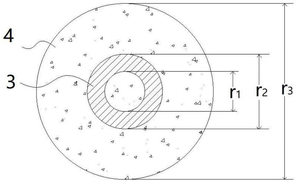
[0047] S2, installation, bonding and combining the PVC pipes into a specified length, then inserting the PVC pipe into the acoustic measuring tube 3 of the first cast-in-place pile 4, and then inserting the PVC pipe with distributed optical fiber 1 into the next cast-in-place pile 4 In the acoustic measuring pipe 3, the PVC pipe is fixed by grouting through the mouth of the PVC pipe 2; a section of the distributed optical fiber 1 is installed in the open groove 202, and after the grouting, ...


PUM

PropertyMeasurementUnit
diameteraaaaaaaaaa
diameteraaaaaaaaaa
diameteraaaaaaaaaa

Abstract

The invention discloses a back-mounted monitoring method for a composite pile. Distributed optical fibers are fixed to the designated position of a PVC pipe; the PVC pipes are bonded and combined into the specified length, then the PVC pipes are inserted into the sounding pipe of the first cast-in-place pile, then the PVC pipes with the distributed optical fibers are inserted into the sounding pipe of the next cast-in-place pile, and the PVC pipes are fixed through grouting of pipe openings of the PVC pipes; and the distributed optical fibers are connected to an optical fiber demodulator, and the stress change in the cast-in-place pile is measured in real time. According to the method, the distributed optical fibers are adopted, the sensitivity is high, the performance is stable, meanwhile, the installation process is simple and easy to implement, new measuring pipes do not need to be additionally arranged, and existing sounding holes in the cast-in-place pile are fully utilized for installation; the method can realize automatic and real-time detection of deformation of a plurality of combined cast-in-place piles, has the advantages of convenience in measurement, high measurement efficiency, small influence of a measurement environment, real-time early warning and the like, realizes an intelligent measurement function, and realizes measurement informatization.

Description

technical field [0001] The invention relates to the field of building construction, in particular to a post-installation monitoring method for composite piles. Background technique [0002] Existing side cantilever bridges are mainly used in environments where geological conditions vary greatly. The length of the cast-in-place piles needs to be planned according to the actual geological conditions during design, thus forming two cast-in-situ piles of different lengths. Due to the complex geological environment, real-time monitoring is required after the cast-in-situ piles are poured. [0003] The existing distributed optical fiber is usually pre-fixed on the steel bar, and the excess concrete on the surface is removed after the concrete is poured. This makes the distributed optical fiber very easy to damage and fail during construction, and the survival rate of the instrument is low. Now there are also post-installed distributed optical fibers, which require additional U-s...

Claims


Application Information

Patent Timeline
Patent Type & Authority Applications(China)
IPC IPC(8): G01L1/24E02D33/00
CPCG01L1/242G01L1/247E02D33/00
Inventor 李晓东陈子龙李会侯甲海李惠王瑞强吴红旗刘喜才
Owner 中铁二十二局集团市政工程有限公司
Why Eureka
Try Eureka