
Device convenient for bright spot detection of lithium battery diaphragm

A lithium battery diaphragm and detection device technology, applied in measuring devices, instruments, scientific instruments, etc., can solve the problems of easy omission and shadow, and achieve the effect of preventing scattering and detachment, uniform irradiation, and easy to observe the diaphragm.

Inactive Publication Date: 2022-05-13
深圳市博盛新材料有限公司
View PDF1 Cites 0 Cited by
  • Summary
  • Abstract
  • Description
  • Claims
  • Application Information

AI Technical Summary

Problems solved by technology

[0005] In order to overcome the disadvantage that the existing detection device uses a light strip as the light, when the diaphragm is irradiated, the shadow will easily appear on the diaphragm, which will affect the detection and cause omissions. The technical problem to be solved is: to provide a self-winding and A bright spot detection device that is convenient for lithium battery separators and can prevent omissions by irradiating a large area of ​​light

Method used


Image

  • Device convenient for bright spot detection of lithium battery diaphragm
  • Device convenient for bright spot detection of lithium battery diaphragm
  • Device convenient for bright spot detection of lithium battery diaphragm

Examples


Embodiment 1

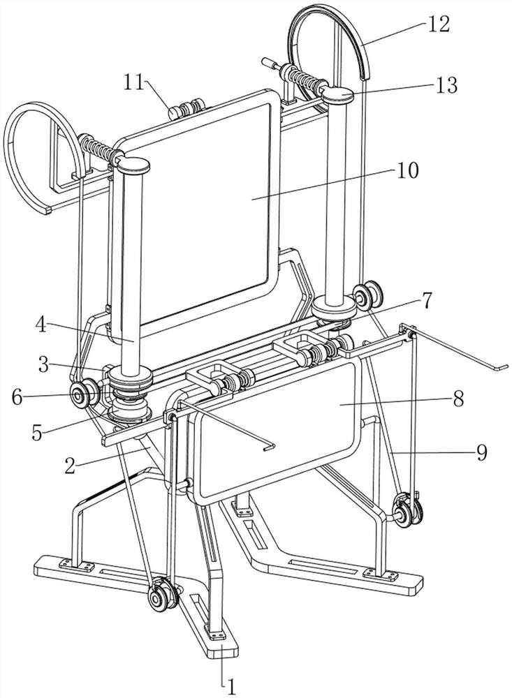
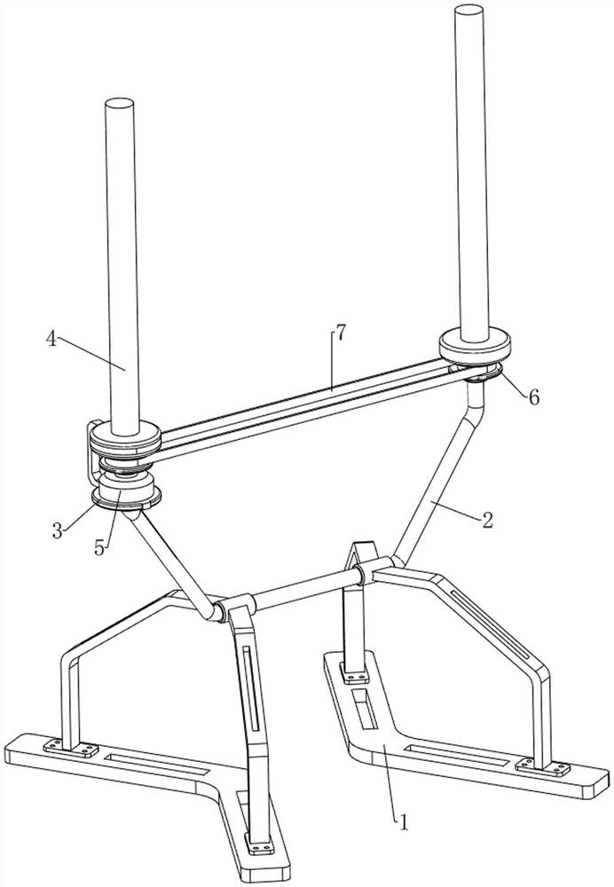
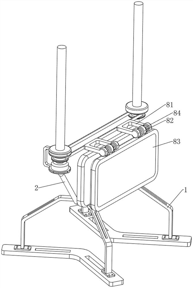
[0038] A bright spot detection device for lithium battery diaphragm, in Figure 1-8 As shown in , it includes a support frame 1, a U-shaped bar 2, a first fixed block 3, a discharge bar 4, a driving motor 5, a pulley 6, a flat belt 7, a detection mechanism 8 and an unfolding mechanism 9, and the lower part of the U-shaped bar 2 The left and right sides are connected with the support frame 1, and the bottoms of the two support frames 1 are coated with anti-slip glue, which can increase the friction between the support frame 1 and the ground, will not move easily, and increase stability. The top left side of the U-shaped bar 2 is welded There is a first fixed block 3, on which a drive motor 5 capable of automatically rewinding and unwinding the diaphragm roll is mounted on the first fixed block 3, and the upper part of the first fixed block 3 and the top right side of the U-shaped bar 2 are both rotatable There is a discharge rod 4 for placing the diaphragm roll for post-rolling...

Embodiment 2

[0043] On the basis of Example 1, in figure 1 and Figure 9 As shown in , it also includes a brightening mechanism 10. The brightening mechanism 10 includes a fifth fixed block 101 and a light-transmitting plate 102. The fifth fixed block 101 is welded on the left and right sides of the upper part of the U-shaped bar 2, and the two fifth fixed blocks 101 are welded. A light-transmitting plate 102 capable of blocking a part of light is connected between the upper sides of the fixing blocks 101 , and the light-transmitting plate 102 is located at the rear side of the two discharge rods 4 .

[0044] After people connect the first lighting lamp 83 with the second lighting lamp 87 and turn on the power supply, the first lighting lamp 83 and the second lighting lamp 87 illuminate the diaphragm at the same time, and the light intensity is relatively strong. People can stand behind the light-transmitting plate 102 and pass The transparent plate 102 is used to check the diaphragm, whi...


PUM


Abstract

The invention relates to a detection device, in particular to a bright spot detection device convenient for a lithium battery diaphragm. According to the bright spot detection device convenient for the lithium battery diaphragm, automatic rolling can be achieved, and omission can be prevented through large-area light irradiation. A bright spot detection device facilitating lithium battery diaphragm comprises supporting frames, a U-shaped rod, a first fixing block, a driving motor and the like, the supporting frames are connected to the left side and the right side of the lower portion of the U-shaped rod, the first fixing block is arranged on the left side of the top of the U-shaped rod, the driving motor is arranged on the first fixing block, and the driving motor can enable a diaphragm roll to be automatically wound. The driving motor works to enable the discharging rods to rotate, in this way, the discharging rod on the right side can unwind a diaphragm roll, the discharging rod on the left side can wind a detected diaphragm, the two discharging rods rotate slowly, and people have enough time to check whether the unfolded diaphragm has quality problems or not.

Description

technical field [0001] The invention relates to a detection device, in particular to a bright spot detection device for lithium battery separators. Background technique [0002] Lithium battery separator is a thin film between the positive and negative electrodes of lithium battery. When the lithium battery undergoes electrolytic reaction, the separator can separate the positive and negative electrodes to prevent short circuit and allow electrolyte ions to pass freely. Due to the internal diaphragm of lithium battery The performance determines the interface structure of the battery, so before the lithium battery separator is shipped, the appearance of the separator must be strictly inspected. [0003] A bright spot detection device for a lithium battery diaphragm with a publication number of CN208350656U includes a bracket on which an unwinding shaft, a winding shaft and a detection light source are arranged. The reel is used to rewind the detected diaphragm, the detection ...

Claims


Application Information

Patent Timeline
Patent Type & Authority Applications(China)
IPC IPC(8): G01N21/84G01N21/01
CPCG01N21/8422G01N21/01G01N2021/845G01N2021/0112
Inventor 张美英陈世章叶淼
Owner 深圳市博盛新材料有限公司
Learn More