Light splitting plate combination structure

A technology of combined structure and beam splitter, applied in optics, nonlinear optics, instruments, etc., can solve the problem of increasing the thickness of the backlight module, and achieve the effect of reducing the thickness, reducing the dark area, and eliminating the dark area.

Active Publication Date: 2022-05-13
FOUR SUN TECH (WUJIANG) CO LTD
View PDF14 Cites 1 Cited by
  • Summary
  • Abstract
  • Description
  • Claims
  • Application Information

AI Technical Summary

Problems solved by technology

In order to eliminate the dark area between the lamp beads, the diffusion plate must be kept as far away from the lamp beads as possible under the action of the short board effect, which leads to a great increase in the thickness of the backlight module

Method used


Image

  • Light splitting plate combination structure
  • Light splitting plate combination structure
  • Light splitting plate combination structure

Examples


Embodiment 1

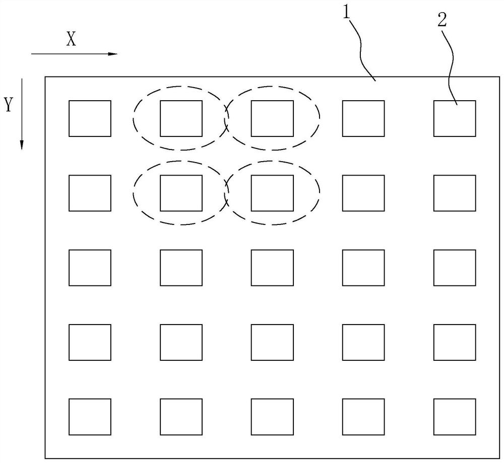
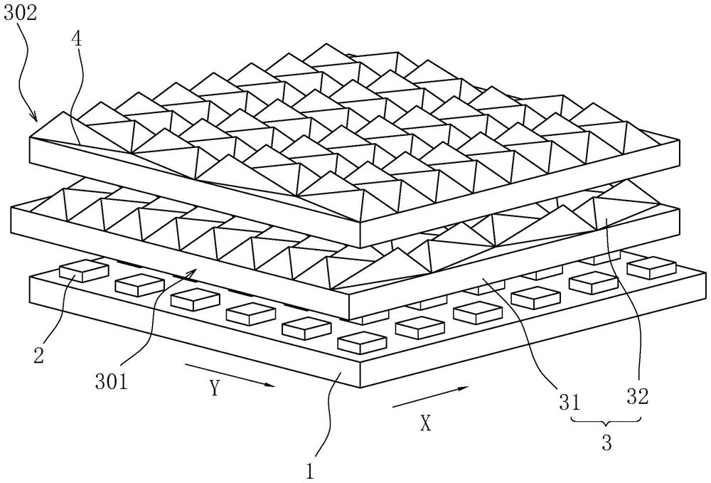
[0045] refer to figure 1 , figure 2 and image 3 , the combined structure of the beam splitter, including a mounting plate 1, a plurality of lamp beads 2 and two beam splitters 3, a plurality of lamp beads 2 are arranged at intervals on the mounting plate 1 in a rectangular array, and two beam splitters 3 are stacked up and down, and set above lamp bead 2. The X direction is parallel to the long axis of the illumination range of the lamp bead 2, and the Y direction is parallel to the short axis of the illumination range of the lamp bead 2. The beam splitter 3 closest to the lamp bead 2 is set within the irradiation range of the lamp bead 2, and diverges the light of the lamp bead 2 along the Y direction. The light diverges in the X direction.

[0046] Since the beam splitter 3 uses its own structure to diverge light, the requirement for the distance between the beam splitter 3 and the lamp bead 2 is relatively small, which can effectively shorten the distance between the ...

Embodiment 2

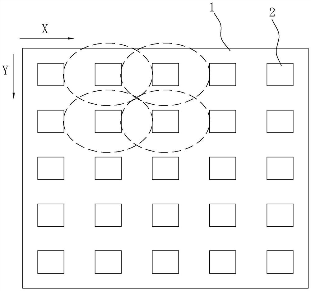
[0054] refer to Figure 5 The difference between Embodiment 2 and Embodiment 1 is that the beam splitting blocks 32 on the second beam splitting plate 302 are arranged staggered along the X direction, and the waists of the bottom contours 4 of adjacent beam splitting blocks 32 overlap. Arranged linearly along the Y direction, the top corners of the bottom profile 4 are connected to the bottom edge of another bottom profile 4 . With such an arrangement, under the same condition that it can be densely distributed on the bottom plate 31, the arrangement of the light splitters 32 is more uniform, so that the divergence of the lights by the light splitters 32 is more uniform, reducing the difference between light and dark after the lights are atomized, and improving Fog effect on lights.

Embodiment 3

[0056] refer to Figure 6 , The difference between Embodiment 3 and Embodiment 1 is that: the bottom profile 4 of the spectroscopic block 32 is an isosceles obtuse triangle or an isosceles right triangle. In the following, an obtuse-angled isosceles triangle is used for illustration.

[0057] refer to Figure 6 , on the first beam splitting plate 301, the beam splitting blocks 32 are arranged in a staggered manner along the X direction, and the waists of the bottom contours 4 of the adjacent beam splitting blocks 32 overlap, and the beam splitting blocks 32 are linearly arranged along the Y direction, and the adjacent beam splitting blocks 32 The apex angles of the bottom contours 4 are opposite, and the bottom lines of the bottom contours 4 of two adjacent spectroscopic blocks 32 coincide, so that the adjacent bottom contours 4 are spliced ​​into a rhombus.

[0058] Under the same specification, the beam splitter 32 whose bottom profile 4 is an obtuse-angled isosceles trian...


PUM


Abstract

The invention relates to the field of optical elements, in particular to a beam splitter combination structure which comprises a mounting plate and a plurality of lamp beads, the lamp beads are arranged on the mounting plate at intervals in an array mode, the direction parallel to the long axis of the illumination range of the lamp beads is the X direction, and the direction parallel to the short axis of the illumination range of the lamp beads is the Y direction. The LED lamp further comprises at least two overlapped light splitting plates, one light splitting plate is arranged in the irradiation range of the lamp beads and diverges light of the lamp beads towards the X-direction side, and the other light splitting plate is arranged in the irradiation range of the adjacent light splitting plate and diverges light of the lamp beads towards the Y-direction side. The backlight module has the effect that the thickness of the backlight module can be reduced under the condition that a good atomization effect is kept.

Description

technical field [0001] The present application relates to the field of optical elements, in particular to a light splitter assembly structure. Background technique [0002] With the rapid development of technology, the demand for LED direct-lit backlight modules is gradually increasing, and the volume of LED direct-lit backlight modules is also getting smaller and smaller. [0003] Traditional LED direct-lit backlight modules are set according to the spacing of a single LED lamp bead, and the illumination range of the LED lamp bead is elliptical, which leads to dark areas between the LED lamp beads. In addition, in the direct type backlight module, the distance between the lamp beads is inconsistent in the long axis direction and the short axis direction of the lamp bead irradiation range. As a result, the area of ​​the dark area around the lamp beads varies in size. [0004] Usually, a diffuser plate is set to atomize the point light source of the LED lamp beads into a su...

Claims


Application Information

Patent Timeline
Patent Type & Authority Applications(China)
IPC IPC(8): G02F1/13357
CPCG02F1/133606G02F1/133607
Inventor 王钰鑫林炳腾
Owner FOUR SUN TECH (WUJIANG) CO LTD
Why Eureka
Try Eureka