
Load-in and load-out cavity and etching equipment system

A technology of load-out and gas-out pipes, which is applied in the field of load-in and out chambers and etching equipment systems, can solve the problem of low exhaust efficiency of residual gas, achieve the effect of reducing wafer defect rate and improving exhaust efficiency

Pending Publication Date: 2022-05-13
SHANGHAI HUALI MICROELECTRONICS CORP
View PDF0 Cites 0 Cited by
  • Summary
  • Abstract
  • Description
  • Claims
  • Application Information

AI Technical Summary

Problems solved by technology

[0004] The purpose of the present invention is to provide a loading and unloading chamber and etching equipment system to solve the problem of low exhaust efficiency of residual gas on the wafer during loading and unloading

Method used


Image

  • Load-in and load-out cavity and etching equipment system
  • Load-in and load-out cavity and etching equipment system
  • Load-in and load-out cavity and etching equipment system

Examples


Embodiment Construction

[0030] In order to make the purpose, advantages and features of the present invention clearer, the present invention will be further described in detail below in conjunction with the accompanying drawings and specific embodiments. It should be noted that the drawings are all in very simplified form and not drawn to scale, and are only used to facilitate and clearly assist the purpose of illustrating the embodiments of the present invention. In addition, the structures shown in the drawings are often a part of the actual structure. In particular, each drawing needs to display different emphases, and sometimes uses different scales.

[0031] As used in the present invention, the singular forms "a", "an" and "the" include plural objects, the term "or" is usually used in the sense of including "and / or", and the term "several" Usually, the term "at least one" is used in the meaning of "at least one", and the term "at least two" is usually used in the meaning of "two or more". In a...


PUM


Abstract

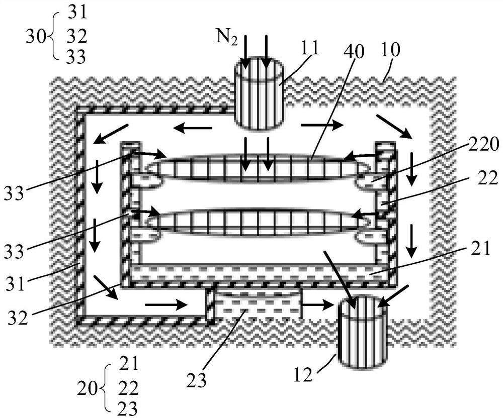
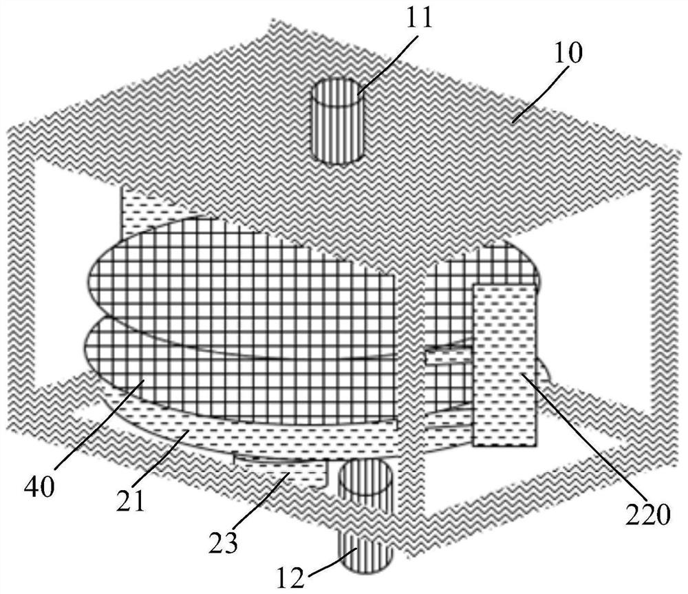
The invention provides a load-in and load-out cavity and an etching equipment system. The load-in and load-out cavity comprises a cavity body, a bearing structure and a pipeline structure, the cavity body is provided with an air inlet and an air outlet; the bearing structure is located in the cavity body, the bearing structure can form at least one placement layer which is arranged at intervals in the vertical direction, and the placement layer is used for bearing wafers; the pipeline structure comprises an air inlet pipe section, an air distributing pipe section and at least one air outlet pipe section. One end of the air inlet pipe section is positioned within the range of the air inlet; the other end of the air inlet pipe section is communicated with the air distributing pipe section which is communicated with the air outlet pipe section; and at least one air outlet pipe section is arranged within the range of the placement layer. According to the configuration, each placement layer can be provided with at least one gas outlet pipe section by adding the pipeline structure, so that wafers on each placement layer can be aligned and purged by nitrogen from the gas outlet pipe section, the discharge efficiency of residual gas on the wafers is improved, and the defect rate of the wafers is reduced.

Description

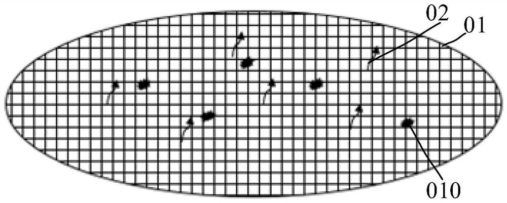
technical field [0001] The invention relates to the technical field of semiconductors, in particular to a loading and unloading cavity and an etching equipment system. Background technique [0002] In a semiconductor manufacturing plant, the main equipment is manufacturing equipment, and most of the manufacturing equipment has a loading and unloading chamber for fixedly placing the wafer, and finally moving the wafer to the process chamber for dry etching. figure 1 is a schematic diagram of a wafer with defects, such as figure 1 As shown, as the size of the wafer 01 becomes larger and larger, the surface of the wafer 01 is also larger and larger, and the wafer 01 after etching is located in the loading and unloading chamber, and the wafer 01 itself will volatilize Residual gas 02, if the residual gas cannot be removed in time, the upper and lower adjacent wafers will affect each other, which will easily cause wafer defects 010. [0003] The current loading and unloading ch...

Claims


Application Information

Patent Timeline
IPC IPC(8): H01L21/67
CPCH01L21/67201H01L21/67069
Inventor 邓必文
Owner SHANGHAI HUALI MICROELECTRONICS CORP
Features
  • Generate Ideas
  • Intellectual Property
  • Life Sciences
  • Materials
  • Tech Scout
  • Unparalleled Data Quality
  • Higher Quality Content
  • 60% Fewer Hallucinations
Learn More