Electrical cabinet convenient for assembling multiple electrical cabinets

A technology for electrical cabinets and electrical boxes, applied in the field of electrical cabinets, can solve the problems that electrical cabinets and electrical boxes cannot be spliced ​​to each other, the electrical cabinet fixing methods cannot be satisfied, and the fixing methods are single, so as to achieve the convenience of retention, reduce the difficulty of disassembly, and reduce operation. Simple and convenient effects

Active Publication Date: 2022-05-13
江苏卓尔越电力科技有限公司
View PDF4 Cites 0 Cited by
  • Summary
  • Abstract
  • Description
  • Claims
  • Application Information

AI Technical Summary

Problems solved by technology

[0003] Chinese patent discloses "an electrical cabinet that is easy to assemble", publication number: CN113939133A, the electrical cabinet provided by this patent is easy to assemble, the fixed box is installed in the inner cavity of the casing through fasteners, and then the electrical components are pushed into the In the installation room of the fixed box, the first elastic component and the second elastic component lock the electrical components; the first elastic component and the second elastic component replace the fasteners to fix the electrical components, which is convenient for assembly, but the electrical cabinet has the following features: Disadvantages: 1. When the electrical cabinet is assembled, the first elastic component and the second elastic component are used instead of fasteners to fix the electrical components, but this installation method is very inconvenient during disassembly, which makes disassembly more complicated; 2. The electrical cabinet The fixing method of the cabinet cannot meet the fixing of various situations. For example, during transportation, the fixing method is relatively simple and the fixing degree is relatively weak; 3. The electrical boxes in the electrical cabinet cannot be spliced ​​with each other, and the functionality is weak

Method used


Image

  • Electrical cabinet convenient for assembling multiple electrical cabinets
  • Electrical cabinet convenient for assembling multiple electrical cabinets
  • Electrical cabinet convenient for assembling multiple electrical cabinets

Examples


Embodiment Construction

[0028] The following will clearly and completely describe the technical solutions in the embodiments of the present invention with reference to the accompanying drawings in the embodiments of the present invention. Obviously, the described embodiments are only part of the embodiments of the present invention, not all of them. Based on the embodiments of the present invention, all other embodiments obtained by persons of ordinary skill in the art without creative efforts fall within the protection scope of the present invention.

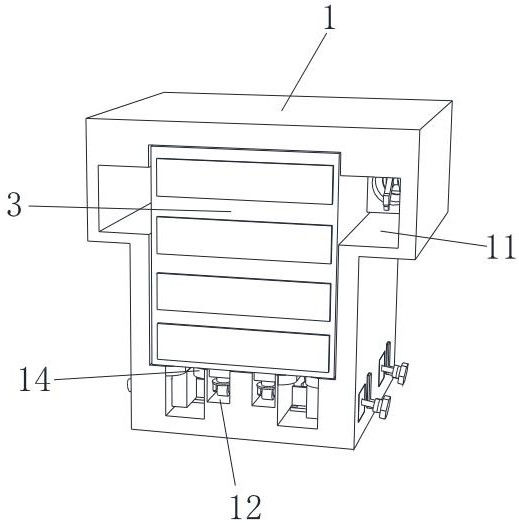
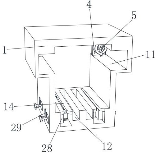
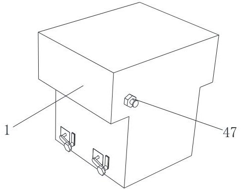
[0029] combine Figure 1 to Figure 9 , a kind of electric cabinet that is convenient for multiple assembly, comprises outer casing 1, and the front end portion of outer casing 1 upper part is provided with side chute 11, and electric box 3 is installed inside outer casing 1, and the inside of outer casing 1 is provided with The side double clamp mechanism that can limit the movement of the electrical box 3, the side double clamp mechanism includes a l...


PUM


Abstract

The invention discloses an electrical cabinet convenient for multiple assembly, which comprises an outer casing, a side sliding groove is formed in the front end part of the upper section of the outer casing, an electrical box is mounted in the outer casing, a side double-clamping mechanism capable of limiting the movement of the electrical box is arranged in the outer casing, and the side double-clamping mechanism comprises a lower fixing seat; the lower fixing base is fixedly installed at the bottom of the inner side wall of the outer machine shell, a spherical groove is formed in the side end of a rubber anti-skid block, so that the end of a connecting rod can shake at will at the side end of the rubber anti-skid block, the connecting rod still drives the rubber anti-skid block to move, the rubber anti-skid block is stressed to slide in a sliding rail between the two upper fixing plates, and the rubber anti-skid block is fixed to the outer machine shell. The rubber anti-skid block slides to block the front of the lower fixing plate, the electric box is further effectively prevented from shaking, and even if the outer shell is transported, the stability of the electric box can be kept through blocking of the rubber anti-skid block.

Description

technical field [0001] The invention relates to the technical field of electrical cabinets, in particular to an electrical cabinet that is convenient for multiple assemblies. Background technique [0002] At present, electrical cabinets have been widely used in industrial fields, and there are more and more functional requirements for electrical cabinets. [0003] Chinese patent discloses "an electrical cabinet that is easy to assemble", publication number: CN113939133A, the electrical cabinet provided by this patent is easy to assemble, the fixed box is installed in the inner cavity of the casing through fasteners, and then the electrical components are pushed into the In the installation room of the fixed box, the first elastic component and the second elastic component lock the electrical components; the first elastic component and the second elastic component replace the fasteners to fix the electrical components, which is convenient for assembly, but the electrical cabi...

Claims


Application Information

Patent Timeline
Patent Type & Authority Applications(China)
IPC IPC(8): H02B1/36H02B1/30H02B1/52H02B1/54H02B1/56
CPCH02B1/36H02B1/308H02B1/303H02B1/52H02B1/54H02B1/565
Inventor 陈雷马明海张子健
Owner 江苏卓尔越电力科技有限公司
Why Eureka
Try Eureka