
Linear frequency modulation signal generating device with adjustable modulation format

A linear frequency modulation signal and modulation format technology, applied in electrical components, electromagnetic wave transmission systems, transmission systems, etc., can solve the problems of low signal performance stability, limited oscillation mode, low system stability, etc., to offset slight environmental interference , the effect of no transmission delay difference, high modulation rate

Pending Publication Date: 2022-05-13
AIR FORCE UNIV PLA
View PDF0 Cites 0 Cited by
  • Summary
  • Abstract
  • Description
  • Claims
  • Application Information

AI Technical Summary

Problems solved by technology

[0004] The above-mentioned schemes have certain limitations: scheme (1) the frequency-time mapping system is complex and poorly tunable, and the system has low stability due to the use of a space-separated structure; scheme (2) the OEO link is difficult to build, and the oscillation mode Limited, it is difficult to generate high-precision LFM signals; the DP-QPSKM modulator in scheme (3) is greatly affected by the drift of the DC bias point, and the stability of the signal performance is not high
In addition, none of the above solutions can achieve switching between multiple modulation formats, and the application scenarios are limited

Method used


Image

  • Linear frequency modulation signal generating device with adjustable modulation format
  • Linear frequency modulation signal generating device with adjustable modulation format
  • Linear frequency modulation signal generating device with adjustable modulation format

Examples


Embodiment Construction

[0032] The present invention will be further described below in conjunction with accompanying drawing:

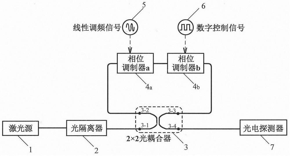
[0033] A chirp signal generating device with adjustable modulation format, such as figure 1 As shown, it includes a laser source 1, an optical isolator 2, a 2×2 optical coupler 3, and a first phase modulator 4 a , the second phase modulator 4 b , Photodetector 7. The reference numerals 3-1, 3-2, 3-3, and 3-4 are the four ports of the 2×2 optical coupler 3, which are respectively marked as the first, second, third, and fourth ports, wherein the first port 3-1 and the second port 3-2 are a pair of ports on the straight-through arm of the 2×2 optical coupler 3, and the third port 3-3 and the fourth port 3-4 are the coupling of the 2×2 optical coupler 3 A pair of ports on the arm. The output end of the laser source 1 is connected to the optical isolator 2; the optical isolator 2 is connected to the first port 3-1 of the 2×2 optical coupler 3; Phase Modulator 4 a connected...


PUM


Abstract

A linear frequency modulation signal generating device with an adjustable modulation format is characterized in that an optical carrier output by a laser source is divided into two paths by an optical coupler after passing through an optical isolator, and the two paths are respectively transmitted in a Sagnac ring structure along a clockwise / anticlockwise direction; the two paths of optical signals transmitted along opposite directions are modulated in different phase modulators; the two paths of modulated optical signals are combined by the optical coupler again and then enter the photoelectric detector for beat frequency, so that linear frequency modulation signals with adjustable modulation formats can be generated; switching among four modulation formats of a phase modulation linear frequency modulation signal, a frequency modulation linear frequency modulation signal, a dual-band phase modulation linear frequency modulation signal and a frequency modulation and phase modulation linear frequency modulation signal can be realized by adjusting a digital control signal of the phase modulator. The method is flexible in control and simple in structure, and can be applied to important fields such as radar communication integrated systems and electronic warfare systems.

Description

technical field [0001] The invention belongs to the technical fields of microwave photonics and microwave signal generation, in particular to a chirp signal generation device with adjustable modulation format. Background technique [0002] Chirp signal has superior pulse compression performance and is widely used in modern radar systems; at the same time, as a spread spectrum carrier, it also has application prospects in the field of wireless communication. Chirp signals combined with other digital modulation formats will improve radar detection performance and give it the ability to communicate wirelessly. For example, FSK modulation of linear frequency modulation signal will improve its anti-interference ability in radar or communication applications; PSK modulation of linear frequency modulation signal will improve the accuracy of radar detection or improve the low probability of interception of its communication. [0003] Compared with traditional electronic technology,...

Claims


Application Information

Patent Timeline
IPC IPC(8): H04B10/556H04B10/516H04B10/50
CPCH04B10/556H04B10/5161H04B10/503Y02D30/70
Inventor 王国栋赵尚弘李轩朱子行周逸潇高从芮李赫孟晴晴薛凤凤
Owner AIR FORCE UNIV PLA
Learn More