Eureka AIR delivers breakthrough ideas for toughest innovation challenges, trusted by R&D personnel around the world.

Switchable gain amplifier

Inactive Publication Date: 2005-06-23
AIROHA TECHNOLOGY CORPORATION
View PDF8 Cites 5 Cited by
  • Summary
  • Abstract
  • Description
  • Claims
  • Application Information

AI Technical Summary

Benefits of technology

[0008] It is therefore an object of the invention to provide a switchable gain amplifier, which uses two cascade amplifier units to provide the amplifier with necessary high gain mode and low gain mode. By means of the switch unit and the control signal for controlling each amplifier unit, the gain amplifier can switch between a high gain mode and a low gain mode according to the strength of the input signal. Therefore, the good linearity of system operation and impedance match of various gain modes can be maintained.
[0010] The second amplifier unit is for providing the second gain mode. The second amplifier unit includes a second input terminal and a second output terminal. The second output terminal, which connects the first output terminal, is for outputting a second output signal corresponding to the second gain mode. Besides, the switch unit is serially connected between the first input terminal and the second input terminal. When the switch unit is turned off and the control signal is in the first level, the gain amplifier is set to be in the first gain mode; whereas when the switch unit is turned on and the control signal is in the second level, the gain amplifier is set to be in the second gain mode. The gain amplifier further includes a first match unit, which is connected to the first input terminal for regulating the first input impedance as the gain amplifier is set in the first gain mode. The second match unit, which is connected between the transistor and the second input terminal, is for regulating the second input impedance the gain amplifier is set in the second gain mode. The first input terminal further connects a bias current source. Therefore, the second amplifier unit can be switched between the high gain mode and the low gain mode to avoid the distortion of the output signal according to the strength of the input signal.
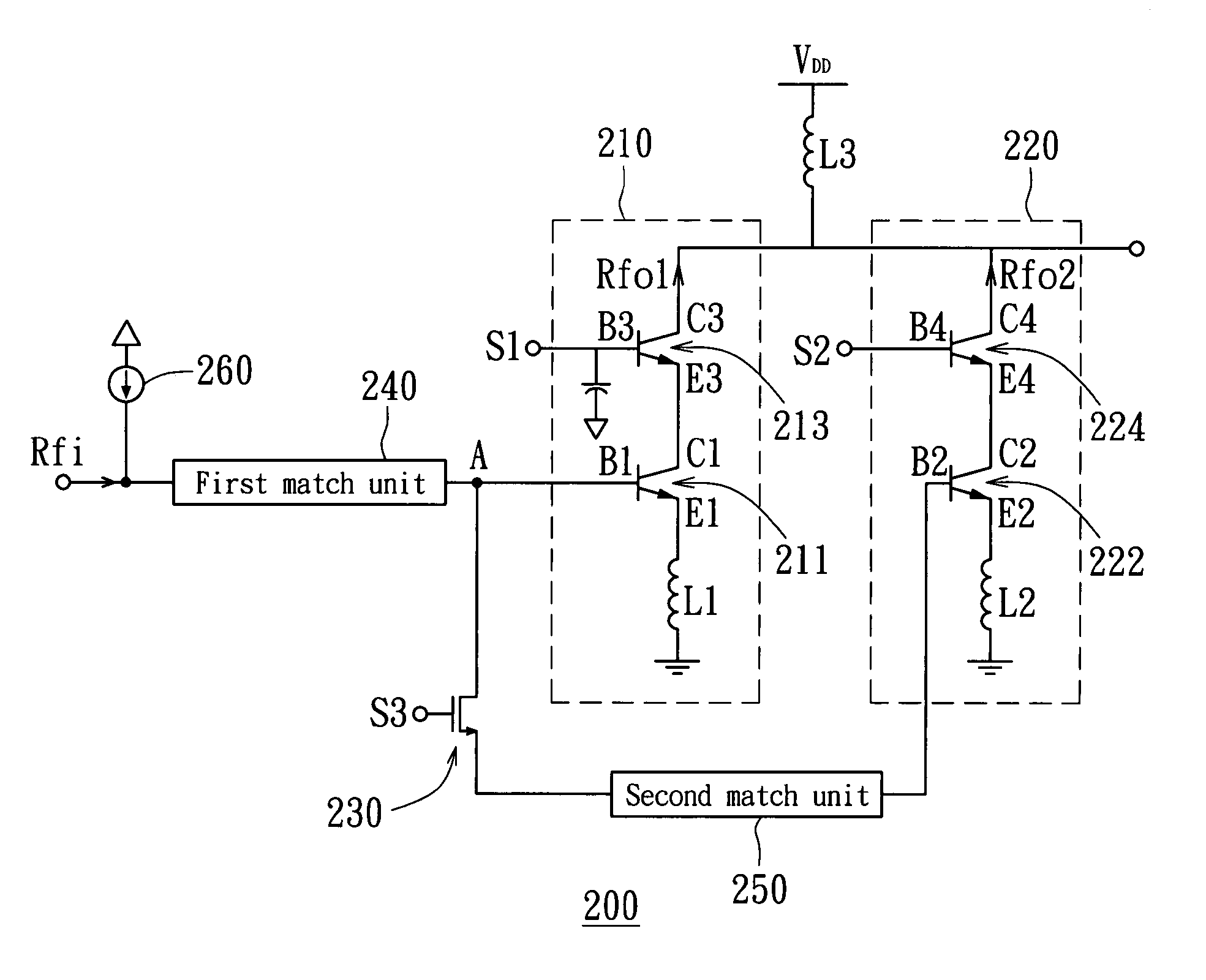
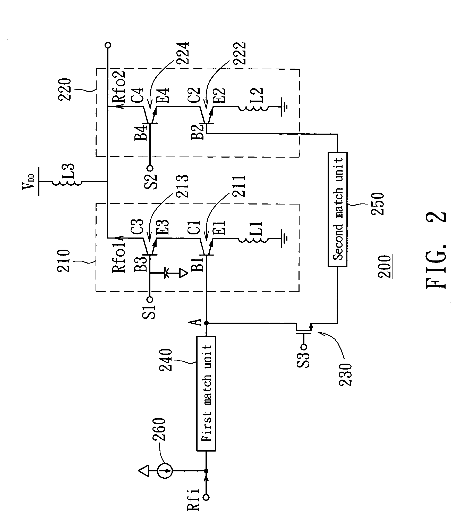
[0013] The first transistor includes a first base, a first emitter, and a first collector. The first base connects the first input terminal, while the first emitter connects the first inductance. The third transistor includes a third base, a third emitter, and a third collecor. The third base connects the first control terminal. The third emitter connects the first collector, while the third collector connects the first output terminal. The second transistor includes a second base, a second emitter, and a second collector. The second base connects the second input terminal, while the second emitter connects the second inductance. The fourth transistor includes a fourth base, a fourth emitter, and a fourth collector. The fourth base connects the second control terminal. The fourth emitter connects a second collector. The fourth collector connects the second output terminal. The first input terminal further connects the bias current source. By means of the first amplifier unit and the second amplifier unit which are cascaded together and the switch unit, the gain amplifier can switch between the first gain mode and the second gain mode to avoid the distortion of the output signal. Meanwhile, the system can have a broader signal bandwidth and a better isolation of input impedance and output impedance.

Problems solved by technology

However, when the system is operated at a high gain mode, the operation of the LNA might be outside the linear region and reduce mobile phone sensitivity if the power of the input signal is too large.
Consequently, the desired sensitivity of signal reception still cannot be achieved.
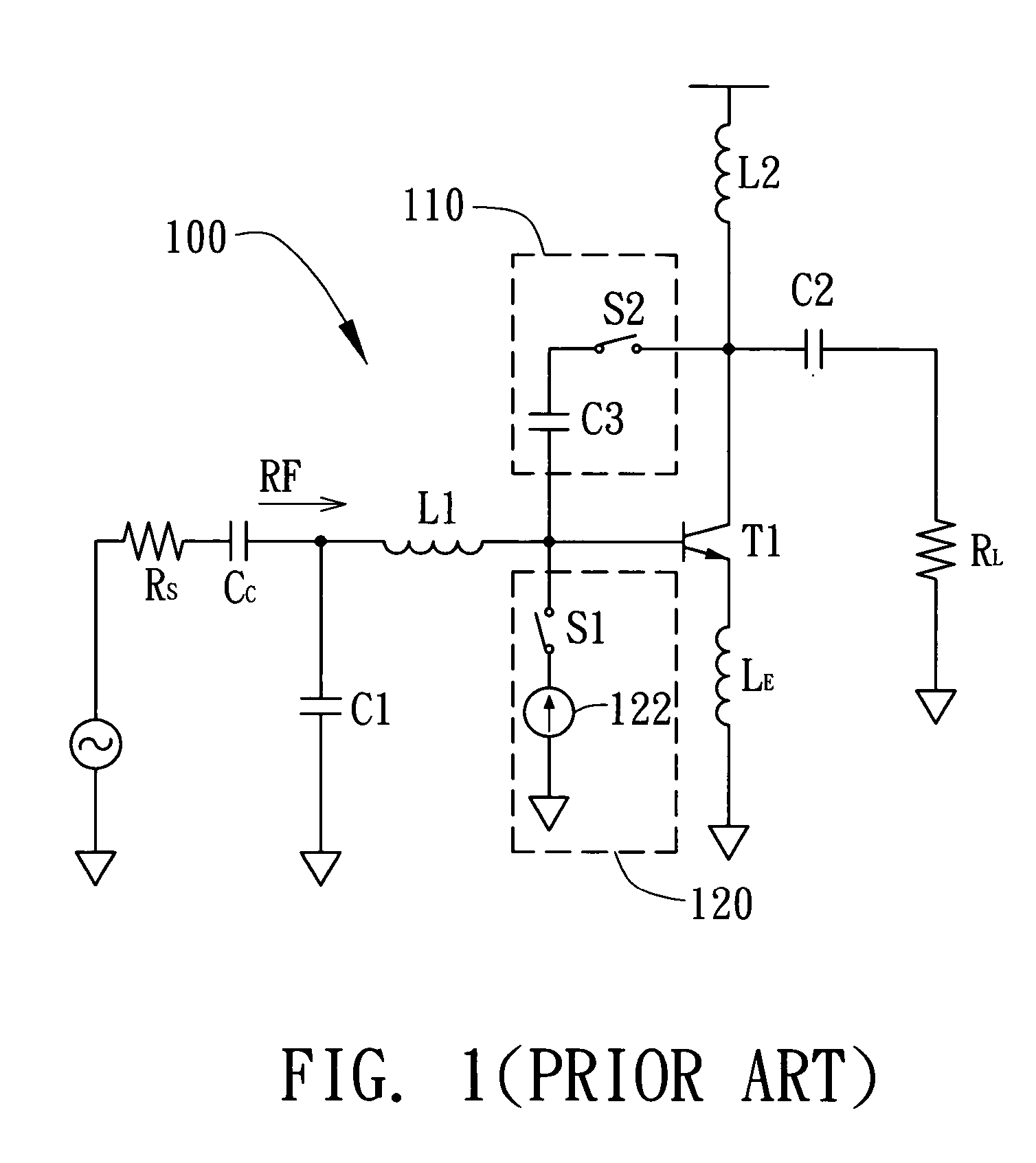
Furthermore, when the switch S1 is turned off, a capacitance value would still remain across the base B and the emitter E of the transistor T1, leading to a poor input impedance match of the gain amplifier 100.

Method used


Image

  • Switchable gain amplifier
  • Switchable gain amplifier
  • Switchable gain amplifier

Examples


Embodiment Construction

[0017] A key feature of the invention is using two cascade amplifier units to respectively provide a high gain mode and a low gain mode. By means of the switch unit and the control signal of respective amplifier unit, the gain amplifier can be switched between a high gain mode and a low gain mode to maintain good linearity of system operation and impedance match of various gain modes according to the strength of the input signal.

[0018] Referring to FIG. 2, a circuit structure of a gain amplifier according to a preferred embodiment of the invention is shown. The gain amplifier 200, a front-end low noise amplifier of a radio frequency receiver for instance, includes a first amplifier unit 210 and a second amplifier unit 220 for providing a high gain mode and a low gain mode respectively. The first amplifier unit 210 includes a first transistor 211 and a third transistor 213, which are cascaded together. The second amplifier unit 220 includes a second transistor 222 and a fourth trans...


PUM


Abstract

A switchable gain amplifier is provided. The first amplifier unit includes a first input terminal to receive input signals, a control terminal, and a first output terminal to output a first output signal corresponding to the first gain mode. The second amplifier unit includes a second input terminal, and a second output terminal to output a second output signal corresponding to the second gain mode. The switch unit is serially connected between the first and second input terminals. When the switch unit is turned off and the control signal is in the first level, the gain amplifier is set in the first gain mode, whereas when the switch unit is turned on and the control signal is in the second level, the gain amplifier is set in the second gain mode.

Description

[0001] This application claims the benefit of Taiwan application Serial No. 92136050, filed Dec. 18, 2003, the subject matter of which is incorporated herein by reference. BACKGROUND OF THE INVENTION [0002] 1. Field of the Invention [0003] The invention relates in general to a switchable gain amplifier, and more particularly to a switchable gain amplifier, which can be switched between a high gain mode and a low gain mode to avoid the distortion of output signals. [0004] 2. Description of the Related Art [0005] In a conventional mobile phone, the signal received by the antenna will be inputted into a front-end low noise amplifier (LNA) of a radio frequency receiver to be amplified so as to suppress noise and improve receiving sensitivity. To achieve the desired level of high sensitivity, the low noise amplifier must provide a high voltage gain for the weak signal received and maintain system linearity to avoid the distortion of the output signal. However, when the system is operated...

Claims


Application Information

Patent Timeline
IPC IPC(8): H03F1/14H03F1/22H03F1/32H03F3/191H03F3/72H03G1/00
CPCH03F1/22H03F3/191H03G1/0088H03F2200/294H03F2200/372H03F3/72
Inventor CHEN, PO-YUWEI, SHU-FEN
Owner AIROHA TECHNOLOGY CORPORATION
Why Eureka
Eureka Blog
Learn More