

Plate cutting machine
A technology for cutting machines and plates, applied to metal sawing equipment, machine tools suitable for grinding the edge of workpieces, and attachments to sawing machines. Spray range, easy to use, good cooling effect
- Summary
- Abstract
- Description
- Claims
- Application Information
AI Technical Summary
Problems solved by technology
Method used
Image

Examples
Embodiment 1
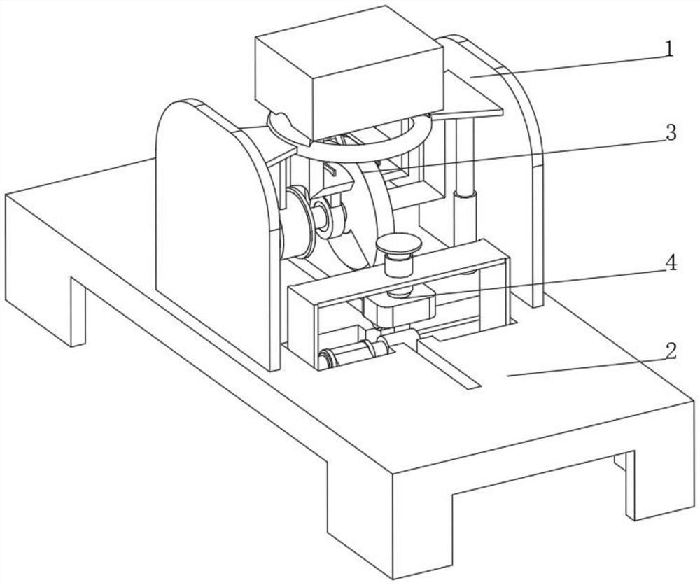
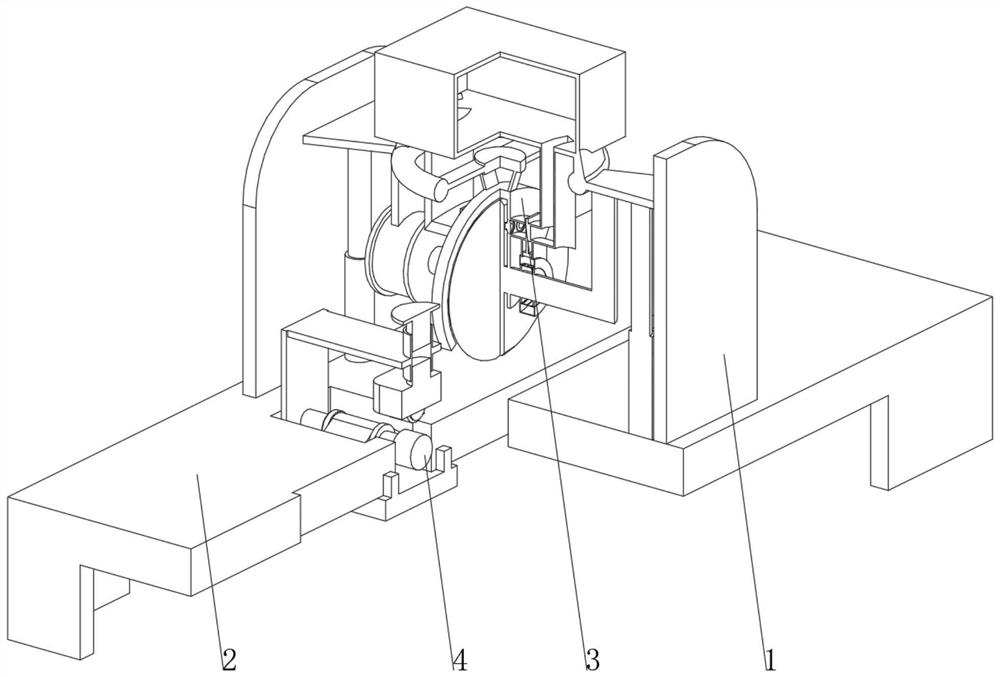
[0034] see Figure 1-Figure 3 , the present invention provides a technical solution: a plate cutting machine, specifically comprising:
[0035] A support frame 1, the bottom of the support frame 1 is fixedly connected with a workbench 2, and the top part of the support frame 1 above the workbench 2 is fixedly connected with a cutting device 3;
[0036] Grinding device 4, the grinding device 4 is arranged on the part of the workbench 2 that is located on one side of the cutting device 3;
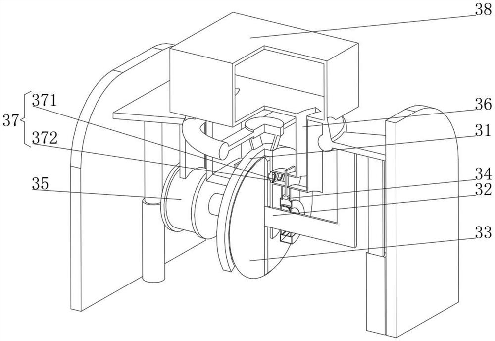
[0037] Cutting device 3 comprises:
[0038] A cutting disc 31 , the center of the inner wall of the cutting disc 31 is rotatably connected to a rotating shaft 32 , the center of the rotating shaft 32 runs through and is fixedly connected to a cutting knife 33 , and the bottom of the cutting knife 33 extends to the outside of the cutting disc 31 ;
[0039] A control device 34, the control device 34 is arranged on one side of the cutting disc 31, and one end of the rotating shaft 32 passes thro...
Embodiment 2
[0046] see Figure 1-Figure 4 On the basis of Embodiment 1, the present invention provides a technical solution: the control device 34 includes a control ring 341, a control cavity 342 is opened inside the control ring 341, and a control tube 343 is connected to the top of the control cavity 342, and the top of the control tube 343 It communicates with the cooling pipe 36, the inner wall of the control pipe 343 is slidably connected with a control piston 344, and the top of the control piston 344 is fixedly connected with a movable baffle 345, the movable baffle 345 is arranged inside the cooling pipe 36 and is slidably connected with the inner wall of the cooling pipe 36, and the movable baffle One side of the plate 345 is slidingly connected with a fixed baffle 346, the fixed baffle 346 is arranged inside the cooling pipe 36 and fixedly connected with the inner wall of the cooling pipe 36, and the inner wall of the control cavity 342 is fixedly connected with a heat conductio...
Embodiment 3
[0048] see Figure 1-Figure 5 On the basis of Embodiment 1 and Embodiment 2, the present invention provides a technical solution: the grinding device 4 includes a grinding table 41, the top of the grinding table 41 is fixedly connected with a pressure seat 42 through a bracket, and the bottom of the pressure seat 42 penetrates and is fixedly connected with a Threaded sleeve 43, the inner wall of threaded sleeve 43 is threadedly connected with threaded ejector rod 44, the bottom of threaded ejector rod 44 is rotatably connected with compression spring 45, and the bottom of compression spring 45 is fixedly connected with compression ejector rod 46, which compresses ejector rod 46 The bottom is fixedly connected with the limited seat 47, the bottom of the limited seat 47 is rotatably connected with a roller 48, the top of the grinding table 41 is fixedly connected with a grinding motor 49, the drive shaft of the grinding motor 49 is fixedly connected with a grinding head 40, and t...
PUM
 Abstract
Description
Claims
Application Information