
Automatic conveying and mounting device for cup cover connecting pieces

A technology of automatic conveying and installation device, applied in workpiece clamping device, transportation and packaging, conveyor objects, etc., can solve the problem that the pin rod is easy to disengage, the pin rod cannot be installed in place, and the pin rod cannot be installed and snapped to the pin hole, etc. problems, to achieve a wide range of applications, improve controllability and stability

Active Publication Date: 2022-05-17
HANGZHOU FREETRON PLASTIC PROD
View PDF11 Cites 0 Cited by
  • Summary
  • Abstract
  • Description
  • Claims
  • Application Information

AI Technical Summary

Problems solved by technology

[0004] There is no pin hole expansion mechanism in the above invention, so if the aperture of the pin hole is set too small, it is easy to cause the pin rod to not be installed in place or If the pin rod cannot be installed and snapped into the pin hole, if the aperture of the pin hole is set too large, the pin rod will easily come out of the pin hole; in addition, the pin rod assembly device in this invention can only align the middle cover and the upper cover Assembling the pin rod in the pin hole, it is impossible to assemble the connector or the pin rod on one side or both sides of the cup lid

Method used


Image

  • Automatic conveying and mounting device for cup cover connecting pieces
  • Automatic conveying and mounting device for cup cover connecting pieces
  • Automatic conveying and mounting device for cup cover connecting pieces

Examples


Embodiment Construction

[0041]In order to make the purpose, technical solutions and advantages of the embodiments of the present invention more clear, the following will clearly and completely describe the technical solutions of the embodiments of the present invention in conjunction with the drawings of the embodiments of the present invention. Apparently, the described embodiments are some, not all, embodiments of the present invention. Based on the described embodiments of the present invention, all other embodiments obtained by persons of ordinary skill in the art without creative efforts shall fall within the protection scope of the present invention.

[0042] In describing the present invention, it is to be understood that the terms "upper", "lower", "front", "rear", "left", "right", "top", "bottom", "inner", "outer" ” and other indicated orientations or positional relationships are based on the orientations or positional relationships shown in the accompanying drawings, which are only for the ...


PUM


Abstract

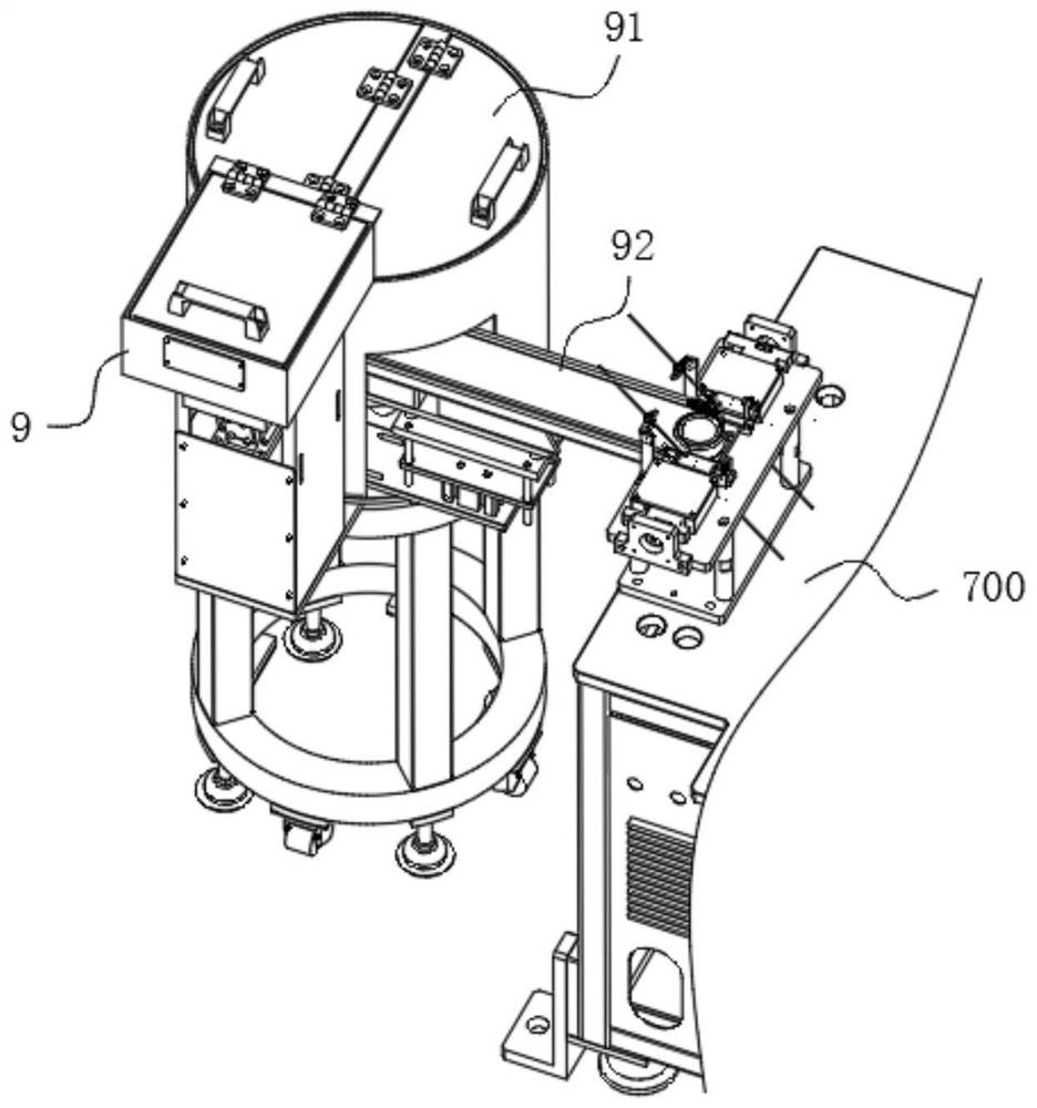
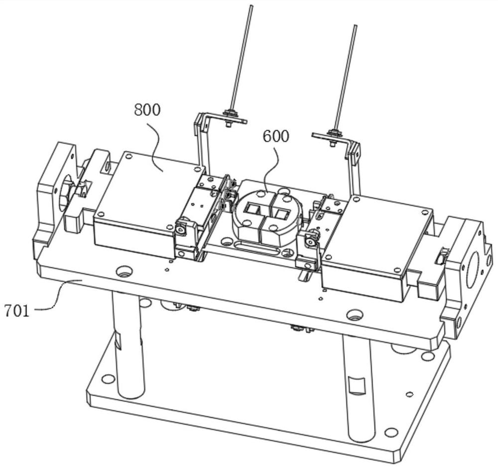
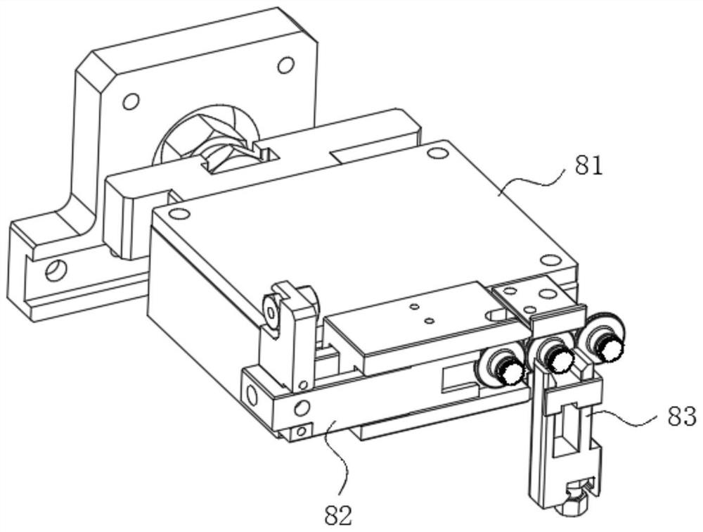
The invention discloses an automatic conveying and mounting device for cup cover connecting pieces. The automatic conveying and mounting device comprises a feeding machine and a mounting mechanism. The feeding machine comprises a feeding machine barrel and a vibration disc. The two sides of the vibration disc are each provided with a conveying channel for conveying the connecting pieces. The mounting mechanism comprises a supporting seat, a reaming structure and a press-in structure; the press-in structure comprises a material pressing component capable of doing reciprocating motion in the transverse direction, a limiting component and a material blocking component. The end, close to the reaming structure, of the material pressing component is provided with a feeding channel which is arranged in the longitudinal direction and used for conveying the connecting pieces. Therefore, the connecting pieces are fed to the mounting mechanism in two ways through the feeding machine, the connecting pieces can be conveniently mounted on the cup cover mounting holes through the hole expanding structure on the mounting mechanism, so that the working efficiency is improved, and the material pressing component of the mounting mechanism can transversely move to assemble the connecting pieces on the two sides of the cup cover; and the limiting component can limit the continuous conveying of the connecting piece and limit the movement of the pressing component in a non-working state, so that the controllability and the stability of the mounting mechanism during operation are improved.

Description

technical field [0001] The invention relates to the technical field of production equipment, in particular to a device for automatically conveying and installing cup lid connectors. Background technique [0002] The cup cover is usually assembled by multiple structural parts such as the upper cover, the lower cover, the handle, and the hardware on the handle. The existing cup cover is usually assembled manually. Hand, the operation is time-consuming and laborious, and the work efficiency is not high. With the development of modern industry, most of the existing cup lid assembly adopts a semi-automatic manual method, which still has the problems of low processing efficiency and high labor cost. Of course, some existing cup lid assembly also adopts a fully automated method. , The assembly of the cup cover is usually performed by multiple stations in an assembly line. The hardware on the cup cover can be automatically assembled into the pin hole of the cup cover, which improve...

Claims


Application Information

Patent Timeline
IPC IPC(8): B23P19/02B25B11/02B23B41/00
CPCB23P19/02B23P19/001B65G47/904B65G47/905B65G47/88Y02E60/10
Inventor 彭龙舒开湘张俊方汪晓波
Owner HANGZHOU FREETRON PLASTIC PROD
Learn More